Consolizing a 2 slots

Akille68

Crazed MVS Addict
Joined
Dec 29, 2012
Posts
141
Hello Folks,
This is my first 3d.
I would like to consolize a 2 slot MVS and some hints will be very appreciated.
I would not like to do the 5 V mod, but maintain the original dual voltage. I have just found a LACIE psu that should have enough power to feed the beast. Here are the specs:
DC Output: 12V(3A) / 5V (4,2A);
AC Input: 110V / 220V

The reason why I will not do the 5v mod is that I wish to maintain full power on audio line in headpone plug, and with th volume trimmer I think I could manage volume without blow TV audio in. Am I wrong?

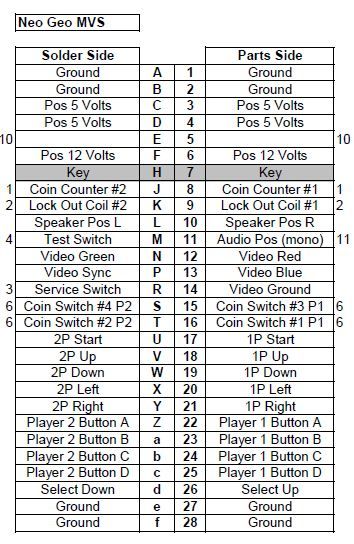
I have read many 3ds about this mod, and know where tap video signals. I am in Italy and RGB is a standard for our TVs. So straight from the tap points to the scart plug, with in series 4 1khom pots for rgb and sinc. I prefer to be able to change tv and make adjustments whenever I want.

So, let start with some questions:

1) where to get 12 volt? From the well known regulator of the MKL's 5v mod? I would like to leave jamma edge alone.

2) power plug will be a 4 pins din connector, so: 5v, 12v, gnd, gnd... Can i split center ground pin on voltage regulator or i will just need to search around with multimeter for another ground to connect at the plug?

3) without doing the 5v mod, where i will get audio signals to the scart? I saw some solder points on Jamma nation tutorial, should it work well on my unmodified MVS too?

4)MVS amplified audio will damage my tv audio circuits if I don't apply 5v mod? I had a 1fz some years ago, connected with a supergun and never had issues with audio, I just checked that trimmer was at his lower position.

5) I have got the 2 slot with unibios on board, but would like to add some buttons for service, coins etc. I have two kids and would like to find an easy way for them to get in without weird button combinations. Sorry for the dummy questions, but I donno Unibios...

6) wires...which kind of wires I need to connect video signals. I thought to strip a scart cable, but they should be shielded and away from power wires?

That's enough, for now. More question will occurr during the work in progress...

Thank You!

Alessandro
 
Last edited:

Fortune

Zero's Secretary
Joined
Jun 30, 2012
Posts
151
...
The reason why I will not do the 5v mod is that I wish to maintain full power on audio line in headpone plug, and with th volume trimmer I think I could manage volume without blow TV audio in. Am I wrong?
...
1) where to get 12 volt? From the well known regulator of the MKL's 5v mod? I would like to leave jamma edge alone.

2) power plug will be a 4 pins din connector, so: 5v, 12v, gnd, gnd... Can i split center ground pin on voltage regulator or i will just need to search around with multimeter for another ground to connect at the plug?

3) without doing the 5v mod, where i will get audio signals to the scart? I saw some solder points on Jamma nation tutorial, should it work well on my unmodified MVS too?

4)MVS amplified audio will damage my tv audio circuits if I don't apply 5v mod? I had a 1fz some years ago, connected with a supergun and never had issues with audio, I just checked that trimmer was at his lower position.

5) I have got the 2 slot with unibios on board, but would like to add some buttons for service, coins etc. I have two kids and would like to find an easy way for them to get in without weird button combinations. Sorry for the dummy questions, but I donno Unibios...

6) wires...which kind of wires I need to connect video signals. I thought to strip a scart cable, but they should be shielded and away from power wires?

That's enough, for now. More question will occurr during the work in progress...

Thank You!

Alessandro

When you do the 5v mod, the amplification and volume slider for the headphone jacks still works perfectly fine. It just bypasses the voltage regulator that was removed by using one of the existing 5v rails, since all of the components in that part of the audio section work on 5v.

The only thing left requiring and still connected to the 12v JAMMA edge is the HA13001 stereo audio amplifier. After the mod, that will still work fine on a Neo-Geo standard JAMMA harness.

If you insist on still using 12v, I would probably connect it to the solder point where the first filter cap from the 12v JAMMA edge is located. It doesn't have to be there, but it's easy to access, trace, and troubleshoot.

I wouldn't tap the audio for output to a TV or amplifier from the output of the HA13001 though. It's too likely to blow something out. The 2-slot boards have large easy to access volume sliders instead of tiny trimmer pots, which are easy to accidentally change.

Personally, I would use the headphone output solder points to tap the audio. At max volume, it still won't hurt an external amplifier when hooked up, and it can be a bit on the quiet side without the boost.

With unibios, you don't need coin buttons. If you only have one cart inserted, the select button acts as a coin button.

Standard insulated hookup wiring should be fine for the short runs to the scart jack. I would still try to keep them away from the power lines and other components to prevent interference.

I hope this is helpful. Good luck! :)
 

Akille68

Crazed MVS Addict
Joined
Dec 29, 2012
Posts
141
When you do the 5v mod, the amplification and volume slider for the headphone jacks still works perfectly fine. It just bypasses the voltage regulator that was removed by using one of the existing 5v rails, since all of the components in that part of the audio section work on 5v.

The only thing left requiring and still connected to the 12v JAMMA edge is the HA13001 stereo audio amplifier. After the mod, that will still work fine on a Neo-Geo standard JAMMA harness.

If you insist on still using 12v, I would probably connect it to the solder point where the first filter cap from the 12v JAMMA edge is located. It doesn't have to be there, but it's easy to access, trace, and troubleshoot.

I wouldn't tap the audio for output to a TV or amplifier from the output of the HA13001 though. It's too likely to blow something out. The 2-slot boards have large easy to access volume sliders instead of tiny trimmer pots, which are easy to accidentally change.

Personally, I would use the headphone output solder points to tap the audio. At max volume, it still won't hurt an external amplifier when hooked up, and it can be a bit on the quiet side without the boost.

With unibios, you don't need coin buttons. If you only have one cart inserted, the select button acts as a coin button.

Standard insulated hookup wiring should be fine for the short runs to the scart jack. I would still try to keep them away from the power lines and other components to prevent interference.

I hope this is helpful. Good luck! :)

Thank U for reply. I read somewhere that with 5v mod audio signal is too much lowered and this makes headset plugs pretty useless...

If I understand well, without a 5v mod I could tapping audio from headphones source without hurting my TV, right?
 
Last edited:

malignantpoodle

Robert Garcia's Butler
Joined
Aug 21, 2010
Posts
1,281
Thank U for reply. I read somewhere that with 5v mod audio signal is too much lowered and this makes headset plugs pretty useless...

If I understand well, without a 5v mod I could tapping audio from headphones source without hurting my TV, right?

I've built 5 of these and have never had a problem with the audio being too low from the headphone audio.
 

Akille68

Crazed MVS Addict
Joined
Dec 29, 2012
Posts
141
Ok. I will follow Your advices and will do the 5V mod. Now, I have the mobo in my hands and unfortunately is not the one that is on "Jamma Nation" tutorials.
This is a shot:


I found some 3ds about this specific model, and there was an hint by MKL to bridge the 5V.
Here is a shot oh him from the following thread: http://www.neo-geo.com/forums/showt...ing-the-5v-only-mod-on-your-consolized-2-slot

Someone modded his MV2 in this way, and wich joint point He used?
Next question:
I found on Mouser a Mean Well PSU with the following specs: 25W 5V 5A
I would like to add an RGB led (like a center pulsing light) and some blue leds at the side of slots and under the mobo. I went to an electronic shop to buy leds and some resistors and the "little man" told me that 5A are too much for leds, that should be warm very soon and blow.
I am not an expert, but I think that He does not considered current drained by machine...now i do not what to do. I saw that there is another Mean Well 5V PSU with 4A. Maybe this could be a better choice? I need an hand...I saw many MV2 beuties with leds on, so I think that is possible to do it. if so, which kind of PSU and resistors i need to buy (I now that it is just a calculation, but did not want to make stupid mistakes).

Last question, I would like to know where tap video signal in this specific model, I did not took a look at the motherboard from the chip side, I think that I will do tomorrow and post some shots, so maybe someone could point me in the right way.

Thank You and take r.
Ale
 
Last edited:

Fortune

Zero's Secretary
Joined
Jun 30, 2012
Posts
151
It looks like you have an MV-2 and not an MV-2F that the tutorial above was made for.

That same image is available on jamma-nation-x as well: http://www.jamma-nation-x.com/jammax/images/2cmvs/mv2-5v.jpg

I couldn't tell you which point the original poster might have used, but there are several options.

I would personally probably use the top one in the picture.

You will still need to remove the voltage regulator, which should be bolted to the board with the top right nut in the picture, and the three solder points to the left of it. The topmost solder point being the top left 5v connection in the picture.

Regarding LEDs, you would need to do some calculations related to the ratings of the specific LEDs being used. It would be the supply voltage minus the voltage drop rating of the LED, and then divide that difference by the number of AMPs the LED is rated. This will give you the minimum rating of resistor needed in Ohms.

Example: LED with a voltage drop of 1.8v at 20 milliamps. Supply voltage of 5v.

We get 5v-1.8v = 3.2v

We need to convert the milliamps to amps for our calculations:
20mA = .02A

Then divide: 3.2v/.02a = 160 Ohms

You would need a resistor of 160 Ohms or more for that LED on a 5v supply.

I would suggest running all LEDs in parallel, each with its own resistor.

I don't have an MV-2 to suggest where one might tap the video signals. I would assume the resistors for RGB to the Jamma edge are the same as on the MV-2F tutorial. The sync might be in a different spot. You could always trace the lines back from the jamma edge and find a location if needed.

Oh... the 5v 4A power supply should be plenty.
 
Last edited:

Akille68

Crazed MVS Addict
Joined
Dec 29, 2012
Posts
141
Thank U for reply. I supposed it was a MV2. :)
About your calculation, I do not understand why amperage erogated by PSU is not considered. I have got some other informations about current passing trhough a diode and 5A are really too much. Even considering that approx 2,5 A will be absorbed by the machine, the remanent 2,5 will make my leds bright like a supernova and then blow....maybe I need a amp reducer at the head of the circuit....every led consumes about 20 mah, x 5 leds the total is 100 mah....maybe I am wrong...
Thank U again for the time you spent for me. Just hope that thsi 3d help some others to not create fire ball using leds on their systems.:mr_t:
 

GohanX

Horrible Goose
20 Year Member
Joined
Sep 28, 2001
Posts
12,521
I'm not familiar with that specific board (mine is a 2f) but finding the RGB lines should be easy. Do a google search for Jamma pinout or pull up a MV2 manual from Hardmvs to find which pins on the jamma connector are RGBS. Use a multimeter to check the continuity between the jamma pin and the resistors, when you find continuity there is your spot. You could solder directly to the jamma pin, but that's weaksauce.
 

Fortune

Zero's Secretary
Joined
Jun 30, 2012
Posts
151
Thank U for reply. I supposed it was a MV2. :)
About your calculation, I do not understand why amperage erogated by PSU is not considered. I have got some other informations about current passing trhough a diode and 5A are really too much. Even considering that approx 2,5 A will be absorbed by the machine, the remanent 2,5 will make my leds bright like a supernova and then blow....maybe I need a amp reducer at the head of the circuit....every led consumes about 20 mah, x 5 leds the total is 100 mah....maybe I am wrong...
Thank U again for the time you spent for me. Just hope that thsi 3d help some others to not create fire ball using leds on their systems.:mr_t:

It's Ohm's Law: I = V/R
or Current is Voltage over Resistance.

So in the scenario above, we have:

Due to the voltage drop from our LED (1.8v), we plug in 5v-1.8v. Which is 3.2v.

If we divide that by the calculated resistor value given above of 160ohms:

I = 3.2v/160ohms

I is 0.02 amps going through our circuit.

LEDs are greedy and have practically no resistance. If hooked directly to a power source without something like a resistor to limit draw, then it will burn out rapidly.

The equation in the posting before was just Ohm's Law with the I and the R distributed so that we could calculate the resistance value using known values.

I = V/R
RI = RV/R
RI = V
RI/I = V/I
R = V/I
 

malignantpoodle

Robert Garcia's Butler
Joined
Aug 21, 2010
Posts
1,281
Why mess with reducing amperage or anything of the sort? Just get a proper psu.

Here;

http://www.ebay.com/itm/5V-3A-AC-DC...=Laptop_Adapters_Chargers&hash=item35bfa6a4f1


mvspinout_zps68a53d8d.jpg


For tapping RGB, just follow the trace running from the edge connector to the resistor and wire in at the resistor. By doing this, you will keep the edge connector clean and the board can still be used in a cab.
 
Last edited:

Fortune

Zero's Secretary
Joined
Jun 30, 2012
Posts
151
Don't worry too much about the amperage rating of the power supply as long as it's over 3A. It's a maximum rating of what can safely be drawn from that supply. The electronics will pull only what they need of it, assuming there isn't some sort of catastrophic component failure somewhere.

You could safely run it all with a computer power supply if you wanted, and those tend to be capable of supplying much more current than your standard wall-wart power supply.

3-4A is about what is suited for this project. For added protection, you could added a 3A fuse to your power supply line.
 

malignantpoodle

Robert Garcia's Butler
Joined
Aug 21, 2010
Posts
1,281
There is no power regulator. Too many amps can be drawn. Someone around here got to 6A and started burning the edge connector.

5v 3a is plenty of power and works. I've even used 5v 2.5a without issue.
 

Fortune

Zero's Secretary
Joined
Jun 30, 2012
Posts
151
There is no power regulator. Too many amps can be drawn. Someone around here got to 6A and started burning the edge connector.

5v 3a is plenty of power and works. I've even used 5v 2.5a without issue.

You make a good point.
Unregulated power adapters can overvolt substantially, and tend to produce more noise. If it's regulated, the amp rating can be higher without much risk.

A little maths to illustrate what happens with the 5V 6A unregulated power supply mentioned above:

W = VA

(Watt is Voltage times Amperage)

W = 5*6
W = 30 watts

We have a 30 watt power adapter. The rating on the unregulated supply is the voltage output at the amperage listed.

Let’s say our circuit uses 2.5A, and we have the 30 watt power supply mentioned above. We have:

30 = V*2.5
30/2.5 = V
V = 12 volts

Since there is no voltage regulator, and the draw of our electronics is only 2.5 amps, the unregulated power supply is supplying 12V instead of the 5V we wanted.

With a regulated power supply, it will nominally output 5V regardless of the amperage draw up to its rated maximum.
 
Last edited:

Xian Xi

JammaNationX,
15 Year Member
Joined
Dec 1, 2005
Posts
27,750
On the MV2 you tap RGB from the same physical locations as the MV2F.

Edit: As for audio, I tap from the headphone jack and leave the volume slider at half.
 
Last edited:

Akille68

Crazed MVS Addict
Joined
Dec 29, 2012
Posts
141
Thank U guys for this so informative thread. I like this community and the fellows that interact in it. I think that I will get a 4A psu, a desktop type, 'cause I hate the wall plug ones. I do not want a psu always working at its nominal max limit. Fortune, do you think that a 4A could be a good choice? And a 4A fuse in line with the phase.
 
Last edited:

Xian Xi

JammaNationX,
15 Year Member
Joined
Dec 1, 2005
Posts
27,750
Thank U guys for this so informative thread. I like this community and the fellows that interact in it. I think that I will get a 4A psu, a desktop type, 'cause I hate the wall plug ones. I do not want a psu always working at its nominal max limit. Fortune, do you think that a 4A could be a good choice? And a 4A fuse in line with the phase.

Fully powered with the +5v mod and 2 games the 2 slots only pulls 1.7A.
 

Akille68

Crazed MVS Addict
Joined
Dec 29, 2012
Posts
141
Fully powered with the +5v mod and 2 games the 2 slots only pulls 1.7A.

Wow, not so much indeed...so, 3A looks more than enough.
Xian, do you know where to tap sinc signal on this specific model?
 

Fortune

Zero's Secretary
Joined
Jun 30, 2012
Posts
151
Fully powered with the +5v mod and 2 games the 2 slots only pulls 1.7A.

Xian Xi knows his stuff.

4A would be overkill, but should be safe if it's a voltage regulated power supply. I'd still add a fuse to be on the safe side.
 

Akille68

Crazed MVS Addict
Joined
Dec 29, 2012
Posts
141
Xian Xi knows his stuff.

4A would be overkill, but should be safe if it's a voltage regulated power supply. I'd still add a fuse to be on the safe side.

Ok folks, let's roll with a 3A one...
 

Xian Xi

JammaNationX,
15 Year Member
Joined
Dec 1, 2005
Posts
27,750
Xian, do you know where to tap sinc signal on this specific model?

Follow the sync pin back and it will lead to a pair of resistors, a 470ohm and a 100ohm. Tap it from the one where the trace connects to first.
 

malignantpoodle

Robert Garcia's Butler
Joined
Aug 21, 2010
Posts
1,281
Fortune said:
You make a good point.
Unregulated power adapters can overvolt substantially, and tend to produce more noise. If it's regulated, the amp rating can be higher without much risk.

A little maths to illustrate what happens with the 5V 6A unregulated power supply mentioned above:

W = VA

(Watt is Voltage times Amperage)

W = 5*6
W = 30 watts

We have a 30 watt power adapter. The rating on the unregulated supply is the voltage output at the amperage listed.

Let’s say our circuit uses 2.5A, and we have the 30 watt power supply mentioned above. We have:

30 = V*2.5
30/2.5 = V
V = 12 volts

Since there is no voltage regulator, and the draw of our electronics is only 2.5 amps, the unregulated power supply is supplying 12V instead of the 5V we wanted.

With a regulated power supply, it will nominally output 5V regardless of the amperage draw up to its rated maximum.

So you're telling me a bunch of things I already know in order to tell me I'm right?
:scratch:
 
Last edited:

Akille68

Crazed MVS Addict
Joined
Dec 29, 2012
Posts
141
Little "step by step" update:

1) Yesterday I removed all mess made by the original owner (an awful Blue paint + fake sticker) and discovered that under it there was red paint too. No primer at all.
Here are some shots of the "before" and "after". Paint was removed in 30 minutes with a liquid paint remover (solvent) with no hurt to the allu alloy.
Before

After


A little work to do with very fine sandpaper, then specific primer for metal, paint (still have to decide which colour) and clear gloss.

2) I removed drum battery, that was still healty and no leaking. Now, I think that I will have to remove the 470 resistor, as explained on JNX. I ask just because my model (MV2) as You know as a different mobo layout. If someone could confirm.


3) I removed power regulator and made a continuity check with a multimeter. Nothing new from the XGN tutorial, but add a picture for refer. Still need to remove some resistors.


4) I checked RGB resistors with multimeter and can confirm that they are at the same position of JNX tutorial. The weird think is that I did not find matching between pins Green and Blue on my Jamma edge and the service manual scheme. On my board Red is on pin 12 (and that's ok), BLue on 11 (not 13 as stated on the manual) and green M (N on the manual). Is it possible ????????? And again, video sinc pin is on "P" on manual, but at this point I do not where to find it on my jamma edge...
 
Last edited:

Akille68

Crazed MVS Addict
Joined
Dec 29, 2012
Posts
141
This is a picture of what I found out with continuity check


Any idea??? Here we are a bit confused...:conf:
Thanx!
 
Last edited:
Top