Neo geo mvs 1b missing Blue color

Tengugurl

Cheng's Errand Boy
Joined
Feb 9, 2017
Posts
111
Hi!
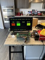
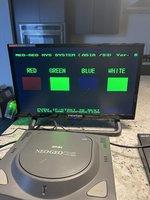
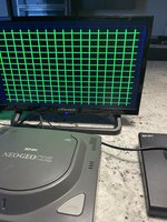
TL;DR how do I get my blue back? Lol it’s missing

1) cleaned pcb ((no corrosion or battery damage, bent pins and or dirty jamma pin connectors

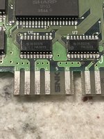
2) recapped it thinking maybe it was a cap issue = no fix

3) read up that it might be a crystal issue, replaced the 24mhz and 32.768hz crystal with no change

4) read up it might be corrosion or battery damage =none so check that off the list

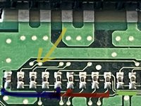
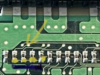
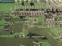
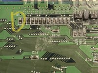
5) measured the resistors on the rgb line resistors and I am thinking that may be what’s up?

Does anyone have a suggestion or thought/ experience on this issue?

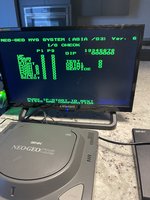
Ps jamma connection is clean, no lose wires and I can play games in perfect color via my super gun. (Localized to this pcb issue wise)

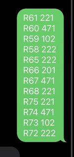
The reading (multimeter) from left to right is
68.1 ohm input of blue
17.72 ohm
17.44 ohm
17.47 ohm
5.76 ohm

They are so tiny and the digits marked off I can’t find their original rating. (Couldn’t find a schematic on the wiki but could be looking in the wrong place)

Why I think it’s the resistors is because I measure some of the red lines and they are in the 200+ ohms region.
 

Attachments

  • F0D4C737-A16E-497D-AC1E-698E336AB386.jpeg
    F0D4C737-A16E-497D-AC1E-698E336AB386.jpeg
    1.7 MB · Views: 17
  • 029D4916-CC7F-4556-84E7-A90668AF271F.jpeg
    029D4916-CC7F-4556-84E7-A90668AF271F.jpeg
    426.2 KB · Views: 19

geladobom

War Room Troll
Joined
Aug 26, 2020
Posts
524
Maybe this?
In the secound picture the first one in your left looks bad in the blue part.
 

Attachments

  • Voltimetro.jpg
    Voltimetro.jpg
    24.6 KB · Views: 2
  • fio-de-arame-1-2mm-aluminio-dourado-ou-prata-2-metros-fio-de-arame-dourado.jpg
    fio-de-arame-1-2mm-aluminio-dourado-ou-prata-2-metros-fio-de-arame-dourado.jpg
    111.7 KB · Views: 2
  • 869161409dfe25db32fca2a006097ebd58dda05a.png
    869161409dfe25db32fca2a006097ebd58dda05a.png
    50.5 KB · Views: 2
Last edited:

ack

Ninja Combat Warrior
15 Year Member
Joined
Apr 9, 2009
Posts
539
The left most component in your picture is a capacitor and not part of the blue color.

Each R, G and B analog signal is comprised from 4 bits, and those 4x resistors determine how much each bit contributes to the analog color signal. If blue is 100% dead I'm doubtful the issue would be those resistors as it would require they all be dead. You will note that each color has 4 resistors and one side of those resistors are all tied together for the given color. This is the analog side and should be going to the jamma edge (I believe there is a resistor on that line before it hits the jamma edge, to the right/down from your picture). I would use your multi-meter and verify the path from the common side of the 4x resistors to the jamma edge.
 

Tengugurl

Cheng's Errand Boy
Joined
Feb 9, 2017
Posts
111
The pic below shows the common color I traced back to the jamma connector.

Yellow area is common from what I got off my multimeter
 

Attachments

  • 9B75D289-AA78-4F8A-B7AF-D04BE1F46CDC.jpeg
    9B75D289-AA78-4F8A-B7AF-D04BE1F46CDC.jpeg
    444.7 KB · Views: 5

Atro

Who?,
20 Year Member
Joined
Jan 30, 2002
Posts
9,214
Luke Morse is far from being an example to anyone.
 

ack

Ninja Combat Warrior
15 Year Member
Joined
Apr 9, 2009
Posts
539
The pic below shows the common color I traced back to the jamma connector.

Yellow area is common from what I got off my multimeter
by traced you mean you verified continuity with your multi meter?

if those looks good other thing you could look at is the source of the blue bits, which should be one of the 74LS273 ICs on the opposite side if the board.

I assume you have tested other boards to verify the issue isnt your supergun?
 

Tengugurl

Cheng's Errand Boy
Joined
Feb 9, 2017
Posts
111
@ack yup, I verified continuity with my fluke multimeter.

Super gun is solid :) that was the first thing I checked. It’s localized to the mvs pcb
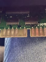
I can check the 74LS273
 

Attachments

  • 6AEECE67-0F78-40C4-B76B-496FD7880E46.jpeg
    6AEECE67-0F78-40C4-B76B-496FD7880E46.jpeg
    970.6 KB · Views: 5
Last edited:

Tengugurl

Cheng's Errand Boy
Joined
Feb 9, 2017
Posts
111
So I had a look and they seemed alright. Reflowed the solder and couldn’t find a schematic to test the connections.

Having read this:

I had a look at my

NEO-GRC2​

And I too had a bridged connection. Sorted that out but no fix :(

So I am going to swap out the 74LS273s to see if it fixes anything.
 

Neo Alec

Warrior of the Innanet
20 Year Member
Joined
Dec 7, 2000
Posts
12,015
I'm sure this is an idiotic suggestion, but... Last time I thought a bunch of my boards had lost a color, it turned out the jamma harness on my supergun just wasn't making good contact with some of my boards.
 

Tengugurl

Cheng's Errand Boy
Joined
Feb 9, 2017
Posts
111
@maki
Ooh thanks! I’ll have a look.

I did get the readings OEM ratings for the resistors so yay! That helped a lot pic wise

So swapped the 74LS273s from a working parts console I had and no fix.

So ruled out:
1) connections on super gun
2) corrosion and or missing parts (all in good repair)
3) bridged connections (fixed that on the Neo-grc2)
4) resistor readings on the resistor array on the base (video rev)
5) caps (full cap kit)


I mean without going HAM and replacing the resistors on the bottom of the pcb that’s all I can think of that displays or plays part in the image

Smart thinking @Neo Alec

Also smart suggestion on the TL866II+ I have one of those too and I may have to see if I can get that adapter to test some components.

I’ll have a look at the PC0 - PC15 go from the NEO-GRC2 to the 273

Also swapped the 74ls05 too and still no fix.
 

Attachments

  • 7A6F3A6C-C09E-4631-8088-9932E5737A0C.jpeg
    7A6F3A6C-C09E-4631-8088-9932E5737A0C.jpeg
    1.3 MB · Views: 3
Last edited:

maki

Edo Express Delivery Guy
Joined
Jan 1, 2022
Posts
334
the PC0 - PC15 traces are connected to the video RAM, NEO-GRC2 and the two 273

no blue at all would make me think that the the traces to the 74LS05 could be the cause
 

Tengugurl

Cheng's Errand Boy
Joined
Feb 9, 2017
Posts
111
So I replaced the 222 and 104 resistor’s and I got blue back :)


Also reflowed the grc2-f but it was the bad resistors on the bottom video dac.

Now I am missing white. Lmfao at least I got blue… I guess haha
 

Attachments

  • B9AB1032-3CFD-4539-A51E-6476A1A6A4E8.jpeg
    B9AB1032-3CFD-4539-A51E-6476A1A6A4E8.jpeg
    1.4 MB · Views: 9
  • 80DC84C5-CE76-480E-A143-D4851C393B84.jpeg
    80DC84C5-CE76-480E-A143-D4851C393B84.jpeg
    1.5 MB · Views: 9
  • 450B8D88-1B11-404A-B22D-2FCE3ED23097.jpeg
    450B8D88-1B11-404A-B22D-2FCE3ED23097.jpeg
    1.4 MB · Views: 9

Tengugurl

Cheng's Errand Boy
Joined
Feb 9, 2017
Posts
111
Tbh 2 more resistors to replace on the blue line. Might just do it to see if it brings back the white?
 

maki

Edo Express Delivery Guy
Joined
Jan 1, 2022
Posts
334
you got some blue back :)

But now the colors aren't balanced, when you measure the R, G and B lines against ground, is one of them sticking out somehow?
They should be all around the same level with your test pic

could be more resistors that need replacement

great job :)
 

Tengugurl

Cheng's Errand Boy
Joined
Feb 9, 2017
Posts
111
Wow!! That is neat. Yup I am waiting on my neo bios mastsa to arrive and I have a few burned unibios bios ICs ready to be popped in here.

Also waiting for the smd resistors to arrive. Ie 2200 ohm one etc…
I couldn’t find the ratings anywhere online but I took my microscope to another mvs I have and was able to get the ratings.

Here they are: *attached

So I might have to back burner this till I get the resistors installed and install that neo bios masta to do the video dac but thanks all for your help ❤️

It means a lot to me as I love fixing things and I love how helpful the neo geo community is towards newbies like me.

Oh quick question…does anyone know the capacitor rating on the far left of the video dac resistors array?

Or a trick to measure it and be like ahh that’s 47uf 25v or something like that
 

Attachments

  • F2BD577A-420B-47FB-984B-B5DC4CB53E14.jpeg
    F2BD577A-420B-47FB-984B-B5DC4CB53E14.jpeg
    77.9 KB · Views: 10
  • D0AB2DAD-C487-43E1-8D57-8038A2BF7E1B.jpeg
    D0AB2DAD-C487-43E1-8D57-8038A2BF7E1B.jpeg
    2.7 MB · Views: 9
  • 698B58CA-A319-4193-884C-B892FA067E12.jpeg
    698B58CA-A319-4193-884C-B892FA067E12.jpeg
    892.5 KB · Views: 9
Last edited:

maki

Edo Express Delivery Guy
Joined
Jan 1, 2022
Posts
334
Or a trick to measure it and be like ahh that’s 47uf 25v or something like that
voltage can be estimated derived from the size, but since on that board 12V was max and only for audio, 5V are more common, anything over that will be fine

regarding the capacitance:
desolder it, but don't remove it from the PCB, in fact turn it an re-solder one leg to the PCB, this way you can measure it out of circuit, and it won't get lost ;)
works for al small two legged parts like resistors, diodes etc. as well
 
Top