MV-1A color problems.

greedostick

Obsessed Neo-Fan
15 Year Member
Joined
Aug 11, 2003
Posts
4,475
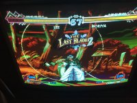
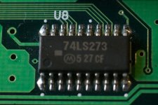
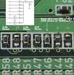
View attachment 35428View attachment 35429View attachment 35430

This is my first MVS system and game. I'm hoping someone here can help me. The closest example I've found is this: http://www.neo-geo.com/forums/showthread.php?234580-MV1A-Display-Problem

Does this look like the same problem?
I don't quite understand what he does in that thread to fix it. Which specific components need to be replaced?

Any help would be appreciated.

I will let someone else chime in. I'm no tech expert, but I can promise that cart is clean and functional.I dismantled, and cleaned it a few weeks back,,and it has always worked perfect for me
 

dakone

n00b
Joined
Mar 14, 2014
Posts
37
No worries, the cart looks great. The problem is with my board. The color issues are present when I turn on the MV-1A without a cart also. (The last screenshot is from the bios only.)
 
Last edited:

aha2940

AH, A, COLUMBIAN!,
Joined
Dec 15, 2013
Posts
2,528
It seems the chips that create the different shadows of the red color are bad. I think mikejmoffitt (user in these forums) can give you more detail about what to check and how to fix it. If he does not chime in to help, try PM'ing him.

Regards.

Edit: It seems the exact same issue that Xian Xi had in the thread you linked. He can help you too.
 
Last edited:

Xian Xi

JammaNationX,
15 Year Member
Joined
Dec 1, 2005
Posts
27,750
Just like in the linked thread, it's the resistors in the video DAC. check all the values for red.
 

bustedstr8

Trollbox Trade Federation,
Joined
Oct 15, 2007
Posts
943
It's something in the DAC section. I would start by checking the red outputs on the 74273 latch. If those are good then check the resistors,traces and solder joints on the analog side. If they are bad you need to work back through the digital side, latch inputs/outputs, palette ram datas/addresses...etc
 

mikejmoffitt

Mickey's Coach
Joined
Feb 6, 2014
Posts
578
The MSB of the red channel is missing. If you are super lucky, the resistor (220 Ohm) or something in its path is damaged. If you are just regular-lucky, one 74273 has a damaged output. If you are kind of lucky, the trace going to the 74273's input for the red MSB is damaged. If you are unlucky, like I once was, the ASIC generating that signal is damaged and requires replacement. In your case, though, this will be Color RAM, and not an entire ASIC. It's far more likely that it's just DAC problems.

EDIT: looks like you are missing actually the MSB and also bit #4, the second most significant. The MSB is why you have two ramps, and the second-to-MSB is why your ramps are of half the number of steps as they should be.

I'm guessing it's the resistors, because it's less likely the '273 has had two outputs fail while the others are fine.

I have a broken MV-1A board here, maybe I'll pin out the DAC and help you identify which parts to look at. I have to pin it out anyhow.
 
Last edited:

dakone

n00b
Joined
Mar 14, 2014
Posts
37
Thanks to all for the help. I'm going to guess I won't be super lucky. If it simply requires replacing a resistor I'm pretty confident I could do it but this seems a bit over my head. I'm a novice solderer at best. Putting together one of these PCBs is my greatest feat to date.

@mikejmoffitt: If you think you can help me through it and it is simple enough I might attempt fixing it. I wanted the 1A model and don't have another source for one.

I got a response from the ebay seller who has been nice enough to honor his warranty terms, should I return it?
 

aha2940

AH, A, COLUMBIAN!,
Joined
Dec 15, 2013
Posts
2,528
I got a response from the ebay seller who has been nice enough to honor his warranty terms, should I return it?

From what I saw on the Xian Xi thread, the board should be repairable, however if the problem is different, as mikejmoffitt described, the fix may not be easy. I would return it and try to get a different board that is already working fine.

Regards.
 

mikejmoffitt

Mickey's Coach
Joined
Feb 6, 2014
Posts
578
Turns out I don't have a 1A, I have another 1-slot. However, the DAC is still principally the same. At the very least, you may be able to diagnose it without any other equipment.

If you have a multimeter, test the resistance of the 220 ohm resistor near the JAMMA edge, which is part of the DAC. There will be three of them, as part of a large bank of resistors, one per R/G/B channel. For the MV-1A, these are surface mount resistors on the bottom of the PCB, in neat little groups. The 220 and 470 ohm resistors are the ones of interest. The '273 D latches are on the top-side, and will be near at least one 74LS06. You can move the two '273s into each other's places and see if the problem moves as well.

Using an LED and a resistor, you can see if the '273's input lines are toggling, as they should be on the color test screen. It's a makeshift logic probe.

This is how the D latches are arranged, and the corresponding input pins for each signal as on my MV-1FZ, with the JAMMA edge facing down. The MV-1A is quite similar so this may help you:

EDcUQzK.png


On a picture of the MV-1A I found it looks like there is a 74LS05 on the right side of the latches, rather than the rest. I can't make any more claims until I've actually used an MV-1A board.
 
Last edited:

mikejmoffitt

Mickey's Coach
Joined
Feb 6, 2014
Posts
578
Some of the traces near the top right of the 74LS273 at U8 look a little funny. Make sure there's no damage or corrosion there, as that would do it. Below them you will find the aforementioned resistors.

I doublt there is anything particularly complicated that is wrong with this, though. At worst, the color RAM (RAM7, RAM8) will have to be replaced. It's probably something simpler like the resistors on the bottom or an issue with traces.

You can identify if the line going to the 273s are floating by touching your hands to it. If you see streaks and blips of odd colors, it's probably a floating input. I doubt that's what it is, since the LS series tends to float high and not low.
 

dakone

n00b
Joined
Mar 14, 2014
Posts
37
O4TsPXf.jpg
tkLVkba.jpg


I found my old macro lens and took some close up pictures of the areas you mentioned. The area around U8 visually seems fine. It may have just been the lighting in that picture.

I think I've found the problem in the resistor banks you mentioned. The banks labeled PC29 and PC27 seem ok, but PC28 is missing 3 resistors. What do you think? Also the area around the screw for the heat sink seems very dirty but isn't missing any components. Does that look like corrosion or just dirt?

Those resistors are extremely small. Is it really feasible to solder these things manually?

Link to high res album with a couple of extra pictures. https://imgur.com/a/VANJx
 
Last edited:

Xian Xi

JammaNationX,
15 Year Member
Joined
Dec 1, 2005
Posts
27,750
Well, at least you know what the fix is, just add the three missing ones. You just need the values. You could use regular sized resistors if it's easier for you.
 

mikejmoffitt

Mickey's Coach
Joined
Feb 6, 2014
Posts
578
Wow! Yeah, that's got to be the problem. Fortunately those resistors are pretty big for surface mount, so if you find the right ones it should not be too tough to replace them.
 

aha2940

AH, A, COLUMBIAN!,
Joined
Dec 15, 2013
Posts
2,528
Those resistors are extremely small. Is it really feasible to solder these things manually?

Link to high res album with a couple of extra pictures. https://imgur.com/a/VANJx

What I do to solder them is tinning the two pads on the board, then I use some pliers to put the resistor in place, and using the soldering iron I heat the pads, so the soldr melts and fixes the resistor/jumper/whatever. Maybe there is a better technique, but that works for me.

Regards.
 

Xian Xi

JammaNationX,
15 Year Member
Joined
Dec 1, 2005
Posts
27,750
What I do to solder them is tinning the two pads on the board, then I use some pliers to put the resistor in place, and using the soldering iron I heat the pads, so the soldr melts and fixes the resistor/jumper/whatever. Maybe there is a better technique, but that works for me.

Regards.

First add flux then put a small amount of solder on one pad then using tweezers hold the new resistor and heat the solder on the pad that you added while placing the resistor down. Then solder down the opposite side then repeat on the first side.
 

dakone

n00b
Joined
Mar 14, 2014
Posts
37
Awesome. I'm going to attempt it. I'm having trouble finding exactly which resistors I will need to order though. The other resistors in those banks are labeled 392,102,471,222,221 etc... How can I make sure I have the right ones in the right places? Does anyone have a picture of a working MV1A or a circuit diagram?
 

channelmaniac

Mr Neo Fix-it
15 Year Member
Joined
Nov 29, 2005
Posts
4,275
The key to surface mount soldering is liquid rosin flux. It helps keep the solder from going cold and peaking/bridging everywhere.

You can clean it up with some alcohol and q-tips.
 

dakone

n00b
Joined
Mar 14, 2014
Posts
37
I'm confused, the resistors on my board don't match the diagram or I'm not reading it right. From what I understand each of the three resistor banks should have the same resistors as in that diagram (in different order?). However the bank that is missing resistors currently has two 3.9k Ohms resistors. The diagram only shows one.
p5dpi12.jpg
 
Last edited:

mikejmoffitt

Mickey's Coach
Joined
Feb 6, 2014
Posts
578
Honestly at this point I'd just use a small piece of wire (without soldering) and jumper across the two resistor pads briefly, and see what lights up. At this point in the DAC bypassing a resistor this way won't harm anything, it'll just make that bit particularly bright

Go to the color bar test, then grab that wire and get ready to experiment with connecting the two resistor pads.

If you connect it, and one half of the red bar section lights up, you've found bit #4.
If you connect it, and the red bar section gains double the amount of sections (matching the ones below in spacing) then you've found bit #1.

That might let you do a little bit of elimination regarding what's there and what's missing. The layout certainly isn't going to match the DAC itself.
 

Xian Xi

JammaNationX,
15 Year Member
Joined
Dec 1, 2005
Posts
27,750
My friend Nicola said:
R44 = 3.7k
R45 = 2.2k
R48 = 220ohm
 
Top