Hi Everyone;
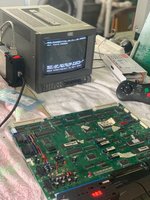
I'm working on a NeoGel MV4-FT4 that I think may have been over voltaged.
It was sold as "parts only". Worked for s breif moment when I got it and has never worked again, over voltage is the only thing I can think of... buy anyway
Symptoms are
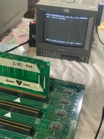
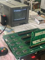
stock bios = fast watchdog
diagnostic bios = fast watchdog
So whatever the problem is must be quite early in the startup chain, it's not even able to boot the bios and start the diagnostics.
Troubleshooting so far
1) Replaced bios and bios socket - no change
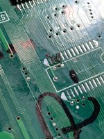
2) checked carefuly with a microscope for trace damage - no change
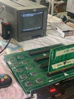
3) swapped all the DIP ram for known good (fast video, pallete, sound) - no change
4) swapped z80 for known good - no change
Next steps from here (I think?)
swap 32k work ram and 32k vram for known good
give up and learn how to use a logic probe
Any other ideas on what might be causing this?
I'm working on a NeoGel MV4-FT4 that I think may have been over voltaged.
It was sold as "parts only". Worked for s breif moment when I got it and has never worked again, over voltage is the only thing I can think of... buy anyway
Symptoms are
stock bios = fast watchdog
diagnostic bios = fast watchdog
So whatever the problem is must be quite early in the startup chain, it's not even able to boot the bios and start the diagnostics.
Troubleshooting so far
1) Replaced bios and bios socket - no change
2) checked carefuly with a microscope for trace damage - no change
3) swapped all the DIP ram for known good (fast video, pallete, sound) - no change
4) swapped z80 for known good - no change
Next steps from here (I think?)
swap 32k work ram and 32k vram for known good
give up and learn how to use a logic probe
Any other ideas on what might be causing this?
")
.jpeg")


")