Neo AES PLL daughterboard removal

Joined
Apr 2, 2023
Posts
9
Hi all,

I got a fabulous deal (relatively) a few months back on a supposedly broken AES that I think the seller just had a broken PSU for, anyway it's been working great and the case is in good condition externally, although internally some of the screw posts are broken and the cartridge flaps are missing. I'm working on some 3D printed solutions for these so all good.

The system is a 19xxx NEO-AES board with a stock US bios and FCC sticker which makes me happy, but it's one of the units that was modified with a PL241S daughterboard to clean up the composite video. I've heard that whilst these improve the composite video, the RGB suffers so it's best to remove it if you're using RGB. Today I decided to recap the console and replaced all the video output caps and resistors with the correct values and also to remove the PLL and move its clock crystal to the mainboard, as I've been told that's all that's required.
However, with the clock crystal on the mainboard I was only getting garbled video and static sound so I assume that the clock wasn't working at all. I moved the crystal back and reinstalled the PLL and it's working again, so the issue isn't with the capacitors or resistors I've changed. I'm running video through a PAL Trinitron that accepts PAL, NTSC, composite, S-video, RGB and just deals with it so I'm pretty sure it's not a compatibility issue.

Is there another step I've missed somewhere with the clock swap? I only removed the PLL connections to the mainboard, nothing else. Any thoughts welcome!
 

maki

Edo Express Delivery Guy
Joined
Jan 1, 2022
Posts
334
It's really just placing the crystal on the main board, it is also the master clock, so if that wouldn't work, you'd have other problems.

Can you take a good picture of how the crystal was installed on the mainboard?
 
Last edited:
Joined
Apr 2, 2023
Posts
9
As I said I've moved the crystal back to the daughterboard so I don't have any photos of it on the mainboard, but I just soldered it in to the clock position in the same orientation as it is on the PLL board and I even did the extra wire link that holds it down and grounds the casing.

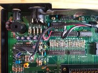
Photo I took before any works, I desoldered all the wires from the daughterboard and then moved the crystal over:
WhatsApp Image 2023-04-03 at 22.38.49.jpeg

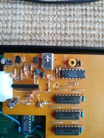
Crystal after replacing onto the PLL:
WhatsApp Image 2023-04-03 at 22.31.09.jpeg

Everything looks normal to me compared to other board photos I can find. I checked continuity on the crystal so I'm sure the solder joints were good.
 

maki

Edo Express Delivery Guy
Joined
Jan 1, 2022
Posts
334
I had a NEOAES here, also with a daughterboard

it had multiple issues, one of them was subtle (to me):
on a superficial glance the video worked fine, but I did notice some weird lines/flickering, another member here helped me a lot by tracing out a signal/clock that was missing

just a few lines where there should not have been any sometimes on the top of screen, no video but I could find one

I've also removed the daughterboard after all issues were fixed

did you use the DIAG Bios to check if things are how they should be?
my issue was not found by the DIAG bios, but it is very really when diagnosing issues
 
Joined
Apr 2, 2023
Posts
9
Solved it!

I compared my board to the photos in the thread you linked and realised that the 100pf ceramic cap just above the clock terminals is present on yours and others' units, looks like it was cut away from mine when the PLL was added since the legs were still soldered in. I had wondered about it but I was comparing to a low-quality photo on the NeoGeoDev wiki and it didn't look like it was present on the basic NEO-AES board. Anyway, luckily the PLL board has a single 100pf cap on it that I was able to rob and now with the crystal back in the video is working great! I'm not sure I can see much difference but it's always difficult without a direct A/B test and the CRT will loosen up the fidelity either way.

I agree with your comment on the thread you linked - there's really not a lot of information on these earlier boards, I'm pretty sure you're the only name I've seen come up consistently when searching, even when I posted on Reddit when I first got the system.

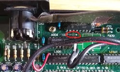
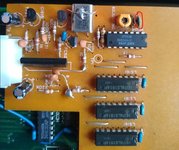
For the sake of anyone stumbling across this thread, below shows the capacitor position (it's non-polar so can go in either way) and also the one you can remove from the daughterboard:

Screenshot 2023-04-04 185730.jpgScreenshot 2023-04-04 185631.jpg

Thanks for your help!
 

maki

Edo Express Delivery Guy
Joined
Jan 1, 2022
Posts
334
I agree with your comment on the thread you linked - there's really not a lot of information on these earlier boards, I'm pretty sure you're the only name I've seen come up consistently when searching, even when I posted on Reddit when I first got the system.
I was just asking around, generous people here helped fixing my problem, slugger_dan even opened his old AES to take measurements and share them here, couldn't have done it without him.

Good stuff on fixing your first gen AES :)

The difference is that without the PLL, the master clock won't be slowing down/speed up to be in sync with the Composite Video sub carrier frequency, so composite video will be a bit worse, but NeoGeo never did composite in the arcade, RGB was the way.
You have a faster master cock crystal in there, 24.168...Mhz instead of 24.00Mhz, that should help a bit with displaying it on LCDs.
 

Neo Alec

Warrior of the Innanet
20 Year Member
Joined
Dec 7, 2000
Posts
12,017
You have a faster master cock crystal in there, 24.168...Mhz instead of 24.00Mhz, that should help a bit with displaying it on LCDs.
In another thread, I reported that the 24.00 MHz has a noisy analog picture on upscalers. The 24.168 MHz gives a cleaner signal. I'm not sure why. Looks just like analog noise.
 

maki

Edo Express Delivery Guy
Joined
Jan 1, 2022
Posts
334
In another thread, I reported that the 24.00 MHz has a noisy analog picture on upscalers. The 24.168 MHz gives a cleaner signal. I'm not sure why. Looks just like analog noise.
I remember you mentioning that, even tried it with both frequencies using a dual frequency oscillator, 24MHz or 24.168..MHz did not make a difference on the same board.

I did notice some boards (MVS and also AES) are just nosier than others (in the case of the AES it was even the same revision, recapped), no idea TBH what the cause is.
 

Neo Alec

Warrior of the Innanet
20 Year Member
Joined
Dec 7, 2000
Posts
12,017
I remember you mentioning that, even tried it with both frequencies using a dual frequency oscillator, 24MHz or 24.168..MHz did not make a difference on the same board.
What screen were you using to test? I couldn't notice anything on an analog CRT. Only on modern screens with a good HD upscaler. I used the Framemeister and the Retrotrink 5X.

I did notice some boards (MVS and also AES) are just nosier than others (in the case of the AES it was even the same revision, recapped), no idea TBH what the cause is.
Yeah, I've noticed the same. I couldn't use my MV-1C to capture footage for my Xeno Crisis due to the sound issue, but I ended up getting my MV-4F out of the cab because my MV-1FS wasn't providing as clean of a picture.
 

maki

Edo Express Delivery Guy
Joined
Jan 1, 2022
Posts
334
What screen were you using to test? I couldn't notice anything on an analog CRT. Only on modern screens with a good HD upscaler. I used the Framemeister and the Retrotrink 5X.
Yeah I use an OSSC with a 55 inch monitor attached to spot this kind of noise.
On my consumer CRT there is no way to see the noise, these have an LPF or around 9-10MHz.
Yeah, I've noticed the same. I couldn't use my MV-1C to capture footage for my Xeno Crisis due to the sound issue, but I ended up getting my MV-4F out of the cab because my MV-1FS wasn't providing as clean of a picture.
Hehe sounds like you also have a small collection of MVS PCBs at home ;)
 
Top