AES Palette RAM error fix?

ucprod

n00b
Joined
Dec 28, 2012
Posts
8
Hello

I posted this in another thread, but this is a more appropriate place for this question:

I have an J-AES system that is not working properly. I get a green screen (Palette RAM error) when I power it up with no cart.

I've searched the forum for a fix to this issue but there doesn't seem to be an easy solution. (I have never handled a soldering iron, let alone modded a system.)

Is there something painless that I am missing? Or is is the only real fix to replace the video ram chips?

Thanks!
 

Xian Xi

JammaNationX,
15 Year Member
Joined
Dec 1, 2005
Posts
27,750
Check for broken traces. You can find palette ram pinouts all over this forum, use google advanced search for best results.
 

ucprod

n00b
Joined
Dec 28, 2012
Posts
8
Hi there, I did look for broken traces -- and I found your tutorial helpful for that -- but couldn't see any.

Would they be located around the video ram chip?
 

Xian Xi

JammaNationX,
15 Year Member
Joined
Dec 1, 2005
Posts
27,750
Did you check the pinouts? What version AES do you have?

Code:
NEO-AES3-6   COLOR RAM

F1

1	VCC
2	HC259 (12)
3	NEO-B1 (12)
4	NEO-B1 (11)
5	NEO-B1 (9)
6	NEO-B1 (8)
7	NEO-B1 (3)
8	NEO-B1 (2)
9	NEO-B1 (159)
10	NEO-B1 (158)
11	LS273 (8) H1, NEO-G0 (35)
12	LS273 (13) H1, NEO-G0 (36)
13	LS273 (14) H1, NEO-G0 (37)
14	GND
15	LS273 (17) H1, NEO-G0 (38)
16	LS273 (3) H2, NEO-G0 (53)
17	LS273 (14) H2, NEO-G0 (54)
18	LS273 (7) H1, NEO-G0 (55)
19	LS273 (18) H1, NEO-G0 (56)
20	GND
21	NEO-B1 (31)
22	GND
23	NEO-B1 (32)
24	NEO-B1 (29)
25	NEO-B1 (28)
26	VCC
27	NEO-G0 (41)
28	VCC

G1

1	VCC
2	HC259 (12)
3	NEO-B1 (12)
4	NEO-B1 (11)
5	NEO-B1 (9)
6	NEO-B1 (8)
7	NEO-B1 (3)
8	NEO-B1 (2)
9	NEO-B1 (159)
10	NEO-B1 (158)
11	LS273 (4) H2, NEO-G0 (62)
12	LS273 (7) H2, NEO-G0 (63)
13	LS273 (8) H2, NEO-G0 (64)
14	GND
15	LS273 (13) H2, NEO-G0 (1)
16	LS273 (17) H2, NEO-G0 (21)
17	LS273 (18) H2, NEO-G0 (22)
18	LS273 (3) H1, NEO-G0 (23)
19	LS273 (4) H1, NEO-G0 (24)
20	GND
21	NEO-B1 (31)
22	GND
23	NEO-B1 (32)
24	NEO-B1 (29)
25	NEO-B1 (28)
26	VCC
27	NEO-G0 (41)
28	VCC
 

ucprod

n00b
Joined
Dec 28, 2012
Posts
8
My system is a NEO-O model with a serial number in the 12XXXX range.

I have visually looked at the traces and I can't locate any breaks. From reading the forum, I figured that the Sony CXK5864BSP-10L chips are the Video Ram. I visually inspected the connectors and couldn't see anything wrong.

Unfortunately, I have no experience with repairing electronics and I'm not sure how to read the chart you attached. Although, I'm willing to learn.
 

Pedrobear

Cheng's Errand Boy
Joined
Mar 1, 2012
Posts
113
You should post your board revision.

Dead ram is an easy fix granted you can find a replacement chip and someone who can service you the swap.
 

Pedrobear

Cheng's Errand Boy
Joined
Mar 1, 2012
Posts
113
Did you locate palette ram? Two 24 pins chips on close to left board edge.

To read Xian Xi chart:

G1 <- chip location (letters and numbers across board edges to locate chips)

1 VCC <- pin 1 of the chip should go to vcc
2 HC259 (12) <- pin 2 of the chip should go to pin 12 of the HC259 chip
3 NEO-B1 (12) <- pin 3 of the chip should go to pin 12 of the NEO-B1 chip
etc etc, have fun :D
 

ucprod

n00b
Joined
Dec 28, 2012
Posts
8
Thanks for the tip! The chart makes sense now.

Since I can't see any broken traces, the next step would probably be to get a logic probe and test the traces that way?
 

kosami

n00b
Joined
Mar 15, 2016
Posts
24
since i still cant make threads, i will revive this one, hope you dont mind guys.

i am stuck here
basicaly, i want to start checking points, with my multimeter, but i will lose sanity, if i dont find the pinouts somewhere

mine is an aes 3-5, are the pinouts same as 3-6? i guess ?

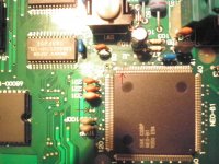
i followed, neo B1 pin 77. pic attached. and i can not find continuity betwen the start and the end on the track
evil-bite-my-baby.jpg
definitivly a problem here, can you confirm me that ?

this baby has a green screen, i will appreciate any input
 

kosami

n00b
Joined
Mar 15, 2016
Posts
24
Did you check the pinouts? What version AES do you have?

Code:
NEO-AES3-6   COLOR RAM

F1

1	VCC
2	HC259 (12)
3	NEO-B1 (12)
4	NEO-B1 (11)
5	NEO-B1 (9)
6	NEO-B1 (8)
7	NEO-B1 (3)
8	NEO-B1 (2)
9	NEO-B1 (159)
10	NEO-B1 (158)
11	LS273 (8) H1, NEO-G0 (35)
12	LS273 (13) H1, NEO-G0 (36)
13	LS273 (14) H1, NEO-G0 (37)
14	GND
15	LS273 (17) H1, NEO-G0 (38)
16	LS273 (3) H2, NEO-G0 (53)
17	LS273 (14) H2, NEO-G0 (54)
18	LS273 (7) H1, NEO-G0 (55)
19	LS273 (18) H1, NEO-G0 (56)
20	GND
21	NEO-B1 (31)
22	GND
23	NEO-B1 (32)
24	NEO-B1 (29)
25	NEO-B1 (28)
26	VCC
27	NEO-G0 (41)
28	VCC

G1

1	VCC
2	HC259 (12)
3	NEO-B1 (12)
4	NEO-B1 (11)
5	NEO-B1 (9)
6	NEO-B1 (8)
7	NEO-B1 (3)
8	NEO-B1 (2)
9	NEO-B1 (159)
10	NEO-B1 (158)
11	LS273 (4) H2, NEO-G0 (62)
12	LS273 (7) H2, NEO-G0 (63)
13	LS273 (8) H2, NEO-G0 (64)
14	GND
15	LS273 (13) H2, NEO-G0 (1)
16	LS273 (17) H2, NEO-G0 (21)
17	LS273 (18) H2, NEO-G0 (22)
18	LS273 (3) H1, NEO-G0 (23)
19	LS273 (4) H1, NEO-G0 (24)
20	GND
21	NEO-B1 (31)
22	GND
23	NEO-B1 (32)
24	NEO-B1 (29)
25	NEO-B1 (28)
26	VCC
27	NEO-G0 (41)
28	VCC

according to this, everything is fine, except for F1 and G1 pin 27, they are not connected also they dont connect to neo-G0 (41)
but again, i own a 5-6

everything else in this list, its wired and OK.
 

Xian Xi

JammaNationX,
15 Year Member
Joined
Dec 1, 2005
Posts
27,750
Neo-G0(41) is probably the most important one. If there is no continuity then connect them.
 

kosami

n00b
Joined
Mar 15, 2016
Posts
24
Thanks a lot Xian Xi, seems like you do own this forum :)

just to recap, aes 3-5. green screen.

if you can point me where to find pinouts for neo-B1, i need to know where supposed to go from 70 to 80 (damaged zone in pics)

and thank you for the pinouts for F1/G1 dude, it saved me lot of time

tomorrow ill check NEO-G0(41) i will follow the traces, just to confirm, before the mad soldering hell falls over me...
 

Xian Xi

JammaNationX,
15 Year Member
Joined
Dec 1, 2005
Posts
27,750
You can get the pinouts from the NG Dev wiki page. Just search on Google.
 

kosami

n00b
Joined
Mar 15, 2016
Posts
24
i double - triple check the list you give
turns out i made a mistake , everything is ok in that list, even neo-G0

i only need to focus on neo-B1, found the pinout, BUT thats it. i dont know still where they should go
you give not only pinouts, but directions, wich is what im looking for.. cant find that on the dev wiki
but nevermind, i already did follow the tracks

obviously i need insane soldering skills, wich i lack.
i will search somebody with the skill, or do train first with some broken ic's.. not ready for this yet.
thanks alot for your input, i will post more when i move ahead.
 

Xian Xi

JammaNationX,
15 Year Member
Joined
Dec 1, 2005
Posts
27,750
i double - triple check the list you give
turns out i made a mistake , everything is ok in that list, even neo-G0

i only need to focus on neo-B1, found the pinout, BUT thats it. i dont know still where they should go
you give not only pinouts, but directions, wich is what im looking for.. cant find that on the dev wiki
but nevermind, i already did follow the tracks

obviously i need insane soldering skills, wich i lack.
i will search somebody with the skill, or do train first with some broken ic's.. not ready for this yet.
thanks alot for your input, i will post more when i move ahead.

Make a diagnostic bios so you can run tests on your AES so you can get an error message.
 

kosami

n00b
Joined
Mar 15, 2016
Posts
24
that involves de-soldering the original bios, dosent?

considering the unit was never open before
i will try first to repair the two broken traces already spotted

i think its just some dust that went into the machine via cartridge slot, and ended up resting on top of the legs of neo-B1
with the time, this little dust corrupted the end of the leg, wich has no continuity with the track
thats all about it, or i hope so

if that goes nowhere, then i will reconsider the bios thing...
 

aha2940

AH, A, COLUMBIAN!,
Joined
Dec 15, 2013
Posts
2,528
that involves de-soldering the original bios, dosent?

It does involve desoldering the original BIOS, putting a socket in place of it and installing an EPROM with the diagnostics BIOS written in it. I would recommend doing it, even if you fix your AES, it will help you install a UniBIOS which IMO is a must for any neo-geo owner.

Regards.
 

kosami

n00b
Joined
Mar 15, 2016
Posts
24
thanks for your input, i think i have an idea
i played before with arduino and my z80, even have the correct zif socket & my willems programmer
my fear is to damage the board fuhrer with my soldering skills.
they are ussualy ok. they do the work. but NEO-B1 is damn small, more than i am used to.
 

kosami

n00b
Joined
Mar 15, 2016
Posts
24
i replaced the broken traces with wires, now i have blue screen

sometimes i keep having the green screen

the point is, most of the time, it will stay blue, sometimes i can heard the sound flicking (i guess its watchdog pushing the reset button)
and my game wont work

i guess i will have to do the bios surgery :(
 

kosami

n00b
Joined
Mar 15, 2016
Posts
24
PD: also pins 79 & 80 from neo-B1 are connected, i dont think they should, 79 is FLIP: Horizontal flip pixel line, and 80 is VCC
but unless i cut the leg, i dont know where they melt

perhaps it should be like that? i cant even search theyr traces, too tired today :(
 
Top