2-slot consolisation project

Adamaki

Haomaru's Blade Shiner
Joined
Oct 7, 2004
Posts
678
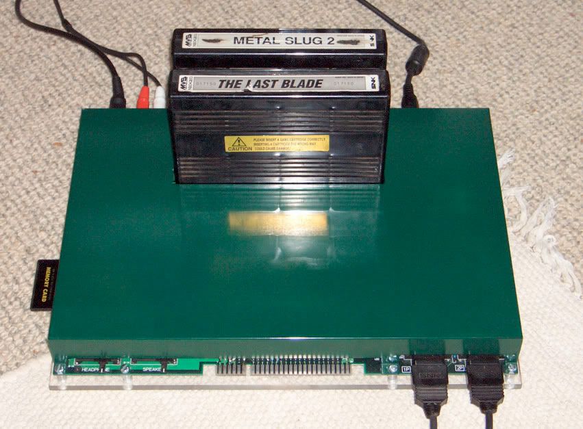
Well I got my 2-slot recently and I've been doing lots of research about how to consolise it but I've still got some unanswered questions. I know you guys are always willing to help out with this kind of thing so I thought I'd start a new thread seeing as I'll probably have plenty more questions as I work on it.

Btw I apologise in advance if I ask any really dumb questions. I don't know that much about electronics and I'm just learning as I go along. I've modified a couple of AES's now so this is my new project :glee:

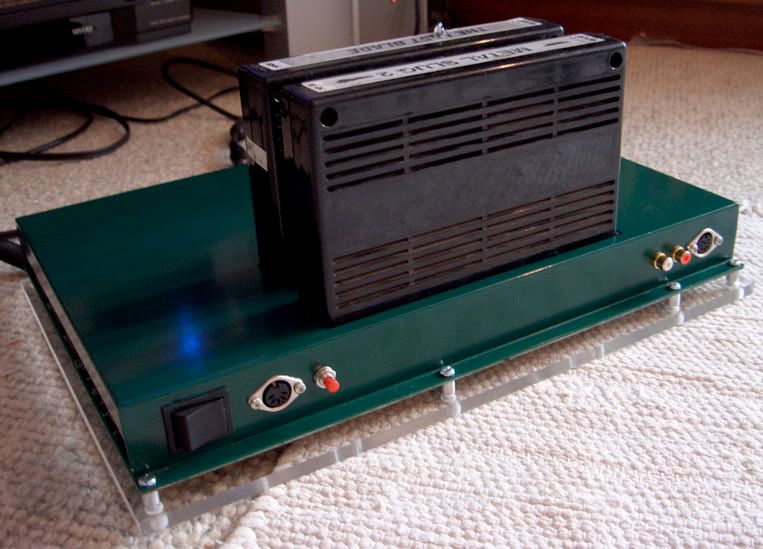
Power supply first. I found this one:

http://www.maplin.co.uk/Module.aspx?ModuleNo=20691&TabID=1&source=15&WorldID=&doy=17m4

Is it suitable? This is the power socket I found:

http://www.maplin.co.uk/Module.aspx?ModuleNo=1407&TabID=1&source=15&WorldID=3&doy=18m4

I found the thread about tapping the sound from the headphone jack so I don't need +12v for the sound chip. Is this the best thing to do so I don't need the +12v?

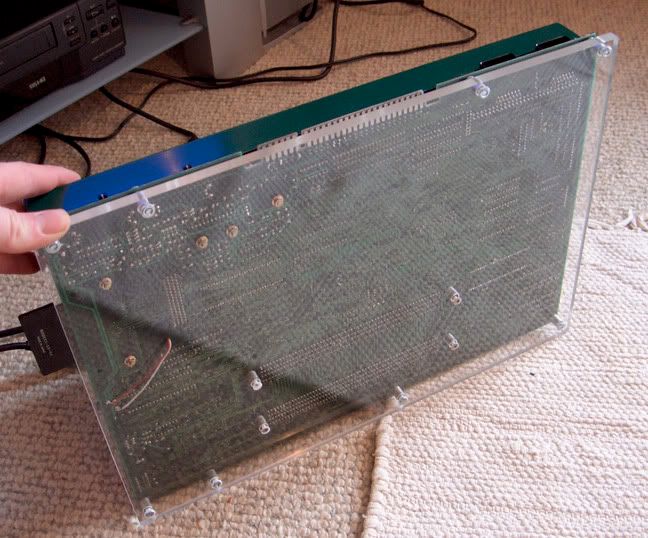
This may be a dumb question but do I connect the ground pins on the JAMMA connector to the negative polarity on the power socket (outer ring)?

Do I need to connect all the ground pins and +5v pins on the JAMMA connector or just one of each?

Ok, onto video output. I'm in the UK so am using rgb straight from the board. I was thinking to add an 82ohm resistor into the red, green and blue lines to reduce the signal for my tv, like with the aes rgb bypass mod.

Any suggestions on what video output socket to use? I was thinking about using an 8 pin din the same as the aes. That way I could use the same scart cable from my aes. Am I correct in thinking I need a ground and +5v wired to the video output? If so would it be best to wire these from the JAMMA connector?

Do I need to install switches for the coin counters, service switch and test switch or can I just set the board to freeplay and forget about these?

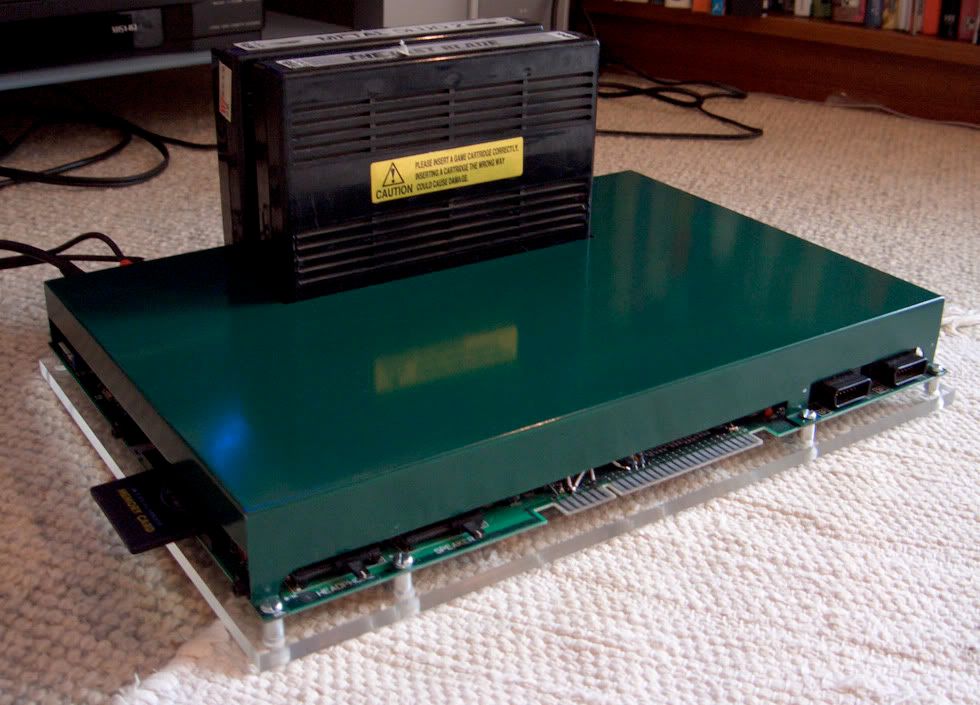
Finally, I was thinking about building a custom case sometime in the future to enclose the whole system, instead of the current case which just covers the top. Is this possible or would it be too difficult?

Sorry for the long post, but I have lots of questions :D

I'd really like to get my 2-slot up and running soon so any help would be much appreciated.
 

stuffmonger

Baseball Star Hitter
Joined
Mar 9, 2005
Posts
1,254
I'm not the most knowledgeable of consolizing, but I do know some stuff since I use my 2-slot, and wire it up alot, and do fun things... I will answer what I can though.
First off
I found the thread about tapping the sound from the headphone jack so I don't need +12v for the sound chip.
... I've also been told that the sound quality is best from the headphone jack (but still not that great unfortunately)
Next
Do I need to install switches for the coin counters, service switch and test switch or can I just set the board to freeplay and forget about these?
The coin counters can be scrapped, but the test switch at least should be kept. Service switch would also be nice, but not all that necessary (I actually havn't used it once since I got my 2-slot) You also would probably want to get a power switch for it... a dpdt is what I've got and it works great (I think a dpst would also work) Also... adding a fuse in the power line would make your consolized 2-slot more safe.
Lastly
I was thinking about building a custom case sometime in the future to enclose the whole system, instead of the current case which just covers the top. Is this possible or would it be too difficult?
yes it would be possible to make a new casing for the mobo... It wouldn't be that difficult to do depending on your creativity and worksmanship abilities, it may be a good idea to add in a fan though if you are going to enclose your mobo... possibly a small laptop fan (which would probably be 12v, and could be powered through the power supply) with vents on the other side.
Hope my info helps :mr_t:
 

powerbvd

n00b
Joined
Mar 19, 2005
Posts
23
1. For the power, anything that gives you +5V and +12V will work.
I recommend this one : http://www.jameco.com/webapp/wcs/st...ogId=10001&productId=125353&searchValue=sc200

2. You only need to connect one ground wire from JAMMA to the power connector.

3. As for the video out. Instead of using resistors of certain value, I suggest you put a 1k ohm potentiometer to each component signal. Please see here http://www.neo-geo.com/forums/showthread.php?t=116979 for detail.

4. Switches. You can wire coin counter to the select button of your joystick and use dip #1 to get the access to the service menu. This way you don';t need to worry about too much about the switches. However, adding switches for those purposes is a easy job and in my opinion a worth doing thing.

5. Case. The easiest way to make customized case is by using Vacuum table. You can buy one here: http://www.warmplastic.com/or.html or make one by yourself by following the tutorial here :http://www.halloweenfear.com/vacuumformintro.html
You can check here http://portablesystems.net/dreamcast.html to see a homemade platic case by this method for a portable dreamcase project.
 
Last edited:

Adamaki

Haomaru's Blade Shiner
Joined
Oct 7, 2004
Posts
678
Thanks for all the help guys :D

That custom dreamcast case is awesome! It looks like a lot of work and money to build something like that though. I was thinking more along the lines of a metal case, similar to the case that comes with the 2-slot, but that contains the whole board.

Thanks for showing me that power supply, powerbvd. I can't find anything like that on the maplin website though. Does anyone know if maplin do +5v and +12v power supplies? Or is there anywhere else in the UK I can get one from?

If I'm going to use +12v as well I have another question. Should I take the sound from the JAMMA connector or the headphone socket? If I take it from the JAMMA connector I assume I will need to build one of those attenuation circuits to reduce the signal to line level?

What about the +5v and +12v pins on the JAMMA connector? Do I need to wire them all to the power supply?

Is it necessary to add a fuse into the power line? I've read that mvs cabinets don't have them so it's not really necessary to have one when consolising it.

I see what you mean about the potentiometers, but is it really necessary? It'd involve lots more drilling on the case. Surely once I get a setting I'm happy with I'd never alter the potentiometer settings anyway.

I'm not 100% sure how the mvs works yet, but if I set the board to freeplay I would have thought I don't need a coin counter switch.

Anyone got any suggestions for video output sockets? What have other people in Europe used to output rgb video?

Cheers :D
 

Adamaki

Haomaru's Blade Shiner
Joined
Oct 7, 2004
Posts
678
Cheers norton. I've read that thread already. What's a continuity test and how do I do it?
 

stuffmonger

Baseball Star Hitter
Joined
Mar 9, 2005
Posts
1,254
It's not necessary to add a fuse... but if you get a power surge, it's more protection... Personally, I'd rather blow a fuse and spend 5 bucks, than blowing my newly consolized 2-slot. You also shouldn't need the coin counters if you set it on freeplay, but I think what powerbvd was saying would also be easy... just connect the coin countersto the player start buttons... I think that would work... I'll have to try it... but I don't think they're absolutely necessary.
 

norton9478

So Many Posts
No Time
For Games.
20 Year Member
Joined
Oct 30, 2003
Posts
34,074
Adamaki said:
Cheers norton. I've read that thread already. What's a continuity test and how do I do it?

Continuity test is a function available on a multimeter....... It's really simple...

If an electical connection exists between the probes (wether they are touching or connected by a wire/trace), then it lights or beeps.....

If your consolizing, you don't have to wire shit to the Jamma Connector....... You can wire it to something that is conencted to the jamma connetor.
 

Adamaki

Haomaru's Blade Shiner
Joined
Oct 7, 2004
Posts
678
norton9478 said:
Continuity test is a function available on a multimeter....... It's really simple...

If an electical connection exists between the probes (wether they are touching or connected by a wire/trace), then it lights or beeps.....

If your consolizing, you don't have to wire shit to the Jamma Connector....... You can wire it to something that is conencted to the jamma connetor.

I don't think mine has that function, it was only a fiver! Couldn't I just use a low voltage setting on the multimeter and detect connections that way?
 

norton9478

So Many Posts
No Time
For Games.
20 Year Member
Joined
Oct 30, 2003
Posts
34,074
Adamaki said:
I don't think mine has that function, it was only a fiver! Couldn't I just use a low voltage setting on the multimeter and detect connections that way?

I'd check the manual...

Nealry every digital multimeter has a contintinuity test...
 

norton9478

So Many Posts
No Time
For Games.
20 Year Member
Joined
Oct 30, 2003
Posts
34,074
and you should get a meter with contintuity test...

YOu shouldn't do this work without it.
 

Adamaki

Haomaru's Blade Shiner
Joined
Oct 7, 2004
Posts
678
norton9478 said:
I'd check the manual...

Nealry every digital multimeter has a contintinuity test...

Yeah I checked the manual and it doesn't have one. Bugger! So much for being economical! I'll see how I get on and if I find I need one with a continuity test I'll just have to invest.
 

dogtoy

Haomaru's Blade Shiner
Joined
Nov 24, 2003
Posts
689
If you don't have a continuity test, you can always improvise one with a few bits of wire, a battery, and a flashlight bulb(you are in the UK so torch bulb :kekeke: ) or LED. Connect one wire to the battery negative, then to one of the bulb connection terminals or the LED anode wire. Connect another wire to the other bulb terminal or LED cathode wire. Now connect a wire to the positive battery terminal.

If you touch the wire from the bulb/LED cathode to the wire on the battery (+) the bulb/LED should light up. Now, to test for continuity in a circuit, place one wire at a point on the circuit and the other wire on another point, the light should come on if there is continuity, if not, there is no continuity (or you didn't make your continuity detector right! :shame: )

(+)------ -----LED (off)
(-)---------------|

(+)------XX----LED (on)
(-)---------------|

The XX is where you touch the wires together

cheers,
-DT

-PS the only way I would actually debug arcade hardware like this is if every electronics store within 3 hours of my home spontaneously combusted. Multimeters are cheap, especially cheap ones, you just have to make sure you get all the options you may need before purchasing one. There are people here with $300+ multimeters, but for most one that costs less than $10 is plenty. Actually I could get a multimeter that will do continuity test and MUCH more at a discount tool shop for about the same price the parts for the improvised continuity detector above would cost at a department store. However if You are in a hurry, and you have a battery, some wire, and a bulb/LED in the room with you and you don't have a multimeter/it's broken, THIS WILL WORK!! :mr_t:
 

Lime2K

Host for Orochi
Joined
Jul 30, 2004
Posts
762
continuity test == resistance test
if the resistance is high, == no connecton
if the resistance is low, -- connection

hope this helps!
 

Adamaki

Haomaru's Blade Shiner
Joined
Oct 7, 2004
Posts
678
dogtoy said:
Multimeters are cheap, especially cheap ones
Really?! Ya don't say! :tickled:


dogtoy said:
you just have to make sure you get all the options you may need before purchasing one.

Thing is I didn't realise I wanted a continuity test when I bought it. D'oh! Thanks for the DIY continuity tester idea though! :kekeke:

Good idea with the resistance test Lime2k. I'll give that a go.
 

Adamaki

Haomaru's Blade Shiner
Joined
Oct 7, 2004
Posts
678
I think I'm pretty much ready to go now. Thanks for all the help guys :buttrock:

I'll have to order my power supply from Jameco because I can't find a similar one from a UK company.

I've just been looking at my JAMMA connector and am bit confused about the switches that someone has installed:

JAMMAconnector.jpg


I can see the first two (from the left) are soldered to the test switch and service switch, but the third wire seems to be soldered to the player 1 button D. Why would anyone want to do this?! :conf:
 

stuffmonger

Baseball Star Hitter
Joined
Mar 9, 2005
Posts
1,254
hmm... that is kinda wierd... maybe they where trying to go for the game select button, but where fatarded. and missed the connector...
 

dogtoy

Haomaru's Blade Shiner
Joined
Nov 24, 2003
Posts
689
Lime2K said:
continuity test == resistance test
if the resistance is high, == no connecton
if the resistance is low, -- connection

hope this helps!

I was going to say this in an edit to my post about the DIY continuimeter (pronounced like "continue-imeter" is that a word??? should be) but got lazy and went to bed. I have personally never seen a multimeter without a test for resistence, and I've always..always used the resistence part to check continuity.

-DT
 
Last edited:

Adamaki

Haomaru's Blade Shiner
Joined
Oct 7, 2004
Posts
678
Hey I know I took my time, but I finally put the last few screws in my 2-slot today. Seeing as it's now complete I took a few photos and posted them up here just because I'm so damn proud of it! :D

Feel free to make comments / suggestions, but please don't slag off my work too much because it's only my first consolisation project!

2-slot1.jpg


2-slot2.jpg


2-slot3.jpg


2-slot4.jpg
 

Yodd

Iori's Flame
20 Year Member
Joined
Feb 7, 2002
Posts
8,214
Looks nice!

I like the dark forest green colour; very snazzy.
 

stuffmonger

Baseball Star Hitter
Joined
Mar 9, 2005
Posts
1,254
SLAG SLAG SLAG!!!

just kidding... nice work... i wish I could get off my lazy ass and do the consolization project I've been trying to plan.
 

Magnaflux

Onigami Isle Castaway
20 Year Member
Joined
Nov 20, 2001
Posts
13,738
Build a supergun for the same amount of money and don't limit yourself to MVS.
 

UncaJJ

Mega Shock!!
Joined
Jul 15, 2005
Posts
100
It looks nice, but what about cooling? How hot will that get with little or no air flow??
 
Top