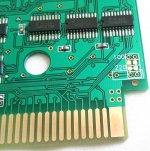
On the other cap positions that go to VCC rails - eg. on prog board C2, C3, CVCC - put 100nF caps there. C1, C4, C5 - not sure, you would have to work out what they are connected to. I would assume if one end of the cap position at C1, C4 and C5 connects to ground, then you could fit 100nF caps there too. Note two diodes on the char board that you could swap out for a 3.3v regulator - but consider the recent article related to mismatch between 3.3v logic and 5v logic and there's a question around whether its better to reduce the voltage to 3.3v to protect the cart, vs reducing to 3.3v and driving the neo chipset harder due to the 3.3v chips clamping more voltage = more current. Personally I would fit a 3.3v regulator, but I cannot 100% suggest its safer than using the diodes.
Note that the prog board has 1 diode - this reduces the 5v to ~4.3v - a similar technique used on the 161 in 1, where they try to find a middle ground between 3.3v and 5v, presumably because the CPLD on there is 5v but they need to connect to 3.3v flash chips or something (speculation). All very messy =/ So regards voltage on the prog board I wouldn't bother with a regulator - chances are at 3.3v that CPLD won't work properly (like on the 161 in 1 if you don't feed one of the CPLDs on there with 4.3v.
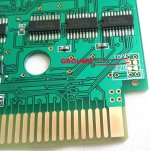
On the char board there are pads on top and underneath that you could probably fit 100nF caps - again check that one side is ground, and perhaps test after fitting one at a time to be sure. On the top side of the char board there are some handy markings and sizes, eg. 100pF, and then a 100 and 220 (not sure if nF or pF.
In summary, I would fit a AMS1117 3.3v regulator to the char board (and remove the two diodes), fit as many 100nF caps in any bypass spots (between a VCC rail and ground), add 2 x 47pF caps between SDRMPX and SDPMPX and ground, perhaps add a 100uF electrolytic on the 5v input to the regulator and a 47uF or 22uF on the 3.3v side of the AMS1117 regulator. Clean up the boards and hope for the best. But I suspect your sound issue will be the 2 x 47pF caps required. It could also be that the 4.3v on the prog board has finally killed one of the VROMs, although they might be 5v parts not 3.3v - no idea. The 4.3v might be purely for the CPLD maybe, in which case maybe the VROMs are OK and its the CPLD that is just undervoltaged and just happens to work at 4.3v.

")