Help me restore a 4 slot!

XtraSmiley

New Challenger
Joined
Jul 6, 2009
Posts
64
EDIT: Updated info below.

OK, so I got a 4 slot cab that has been changed into a 1 slot. All the wires were still in place, so I just bought a 4 slot and want to put it in.


First thing I did was rip the 4 slot's battery out, as was suggested on this forum.
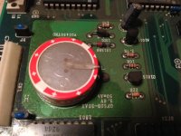
battery.JPG
I didn't have a way to de-solder it, so I just ripped it out. I'll get around to installing a button battery later, but for now I was worried about losing the board to a leaky battery so it had to come out ASAP!
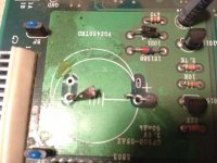
battery out.JPG
I didn't see any leaking, but it was moist under the battery. The stuff you see on the picture is dust, not fuzz though, at least I don't think it was. It did seem to have a wet area around the battery, but nothing was corroded.
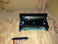

1 slot.JPG
Here is the 1 slot that is in here. Does this have a battery I need to rip out as well? EDIT: It does, but I think I'm just going to sell it and let the next person do with it as they may.

I just plugged this connector into my 4 slot, but is that safe? Do I need to make any changes like to some 5v or something? I guess what I'm asking is, am I ok just doing this swap or should I do something else?
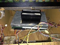
4 slot mostly working.JPG
OK, here is the 4 slot just sitting inside on top of the 1 slot. Just wanted to see if it would work.

It did work, but I had a few odd problems. The SERVICE and TEST buttons don't work right. I figured I didn't plug something up that needed it.
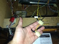
what are these wires.JPG
These two seem to run down toward the SERVICE and TEST buttons, but what do they plug into? EDIT: Turns out they are the plugs for the dollar bill machines, one for player one and two. Plugged them both in and they work, although not with the 1 slot.
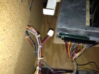
what is this wire.JPG
Also, this one is just hanging, what does it go to? EDIT: As someone posted below, it's the plug that runs from the headphone jack in the front of the machine to the 4 slot. I'm missing the extension piece though, so it doesn't reach right now. I'll have to find one online or make one.

So, I'm not sure what is wrong with the two service buttons, but I also see there is a ground plug on the 4 slot board, but I'm not sure what to plug in it.

I also didn't see the cables for the memory card and headphone jacks, but I have one that came with my 4 slot, but I don't see where to plug the ground wires into. I can take a picture if no one understands what I mean by this, but basically there are the plug in ends of the cables for the baord and the memory card PCB, but then there is a separate, green wire that looks like a ground wire. Not sure what to tie this into.

Thanks to everyone who can help.

I also got TWO sets of the digital number screens (one vertical one horizontal) wires to an entire 4 slot set up (minus what I need to get mine fully running) and two memory card boards and an extra marquee light strip. A Metal Slug X full size marquee and bezel sticker (the 4 slot was converted to a MSX).

What I need to finish my system off is a 4 slot marquee and a 4 slot mini-marquee holder (the clear plastic thing that holds the mini-marquees.

I'll probably post on the for sale thread, but if anyone has the above that I need, please let me know!
 
Last edited:

XtraSmiley

New Challenger
Joined
Jul 6, 2009
Posts
64
Oh, I forgot to mention. Both the coin LEDs work (checked in test mode) but regardless of which side I put money into, only player one LED gets coins added and in game (Puzzle Bobble, Metal Slug X) even though the player 2 side says zero coins, they can join in by pressing player 2, even though this uses player 1's coins.

Obviously I'd like this set to the normal opeartion.
 

slerch666

updyke,
Joined
May 23, 2002
Posts
8,984
Here is the 1 slot that is in here. Does this have a battery I need to rip out as well?
Yes. They all have batteries for the high score and soft dips. Pull that shit out!

I just plugged this connector into my 4 slot, but is that safe? Do I need to make any changes like to some 5v or something? I guess what I'm asking is, am I ok just doing this swap or should I do something else?
Should be fine. From what I know, power and everything else is essentially the same for all Neo boards, with the exception being the 6 slot board.

It did work, but I had a few odd problems. The SERVICE and TEST buttons don't work right. I figured I didn't plug something up that needed it.
Can't help you on this one. Did Service and Test work on the 1 slot?

I also didn't see the cables for the memory card and headphone jacks, but I have one that came with my 4 slot, but I don't see where to plug the ground wires into. I can take a picture if no one understands what I mean by this, but basically there are the plug in ends of the cables for the baord and the memory card PCB, but then there is a separate, green wire that looks like a ground wire. Not sure what to tie this into.
I've never seen an auction for a 4 slot that includes the cables. I also don't have a memory card option for my 4 slot (I use the 4 slot on my Super Nova Super Gun and the 2 slot I have in my cab has memory card built in).

What I need to finish my system off is a 4 slot marquee and a 4 slot mini-marquee holder (the clear plastic thing that holds the mini-marquees.
I vaguely recall there being a website linked from here to a place that sells reproduction overlays for Neo Geo control panels. Can't find the link now, but it's possible they also have reproduction 4 slot marquees. Not sure. Sorry.
 

Heinz

Goobs! They're everywhere!
20 Year Member
10 Year Member
15 Year Member
1 Year Member
Joined
Feb 13, 2005
Posts
22,868
Service and Test buttons are wired to that 56 pin connector you hooked up to your 4 slot. It is called a JAMMA connector and is pretty much where everything comes back to. Read up on the JAMMA 56 pin wiring pinout, you will learn a lot.

I'm familiar with candy cab wiring, not so much the mess that these woodys can be but that hanging 4 pin connector looks like the 4 Pin headphone/stereo speaker output. Though please trace it back to where its going before connecting and praying. The only thing I'd worry about with just connecting boards to that JAMMA connector is the voltage level, get a multi meter and make sure 5v is no more than 5.00-5.10, any higher and you're likely to kill something.
 

arcade game

Galford's Armourer
10 Year Member
Joined
Apr 28, 2012
Posts
466
@ extrasmiley, if you want all the cables uncut from a original 4 slot
let me know.it comes with everything in cluding the control panel with joysticks
Digital coin counter ,memory car slot.top 4 slot marquee including the led,with transformer.i mean everything from a 4 slot
 

BeefyWhale

Rugal's Thug
Joined
Apr 26, 2010
Posts
92
If your looking for a lot of new parts for your cab I'm selling a bundle of Neo geo cab stuff. Let me know
 

XtraSmiley

New Challenger
Joined
Jul 6, 2009
Posts
64
Thanks for the offers guys, but I have the cables for like two sets of cabinets. I just need to get them all plugged in right.

When I use the service button for the 1 slot, I think only one button works right. I'll do some more testing and post Monday when I get back home.
 

mjs256

Kula's Candy
10 Year Member
Joined
Apr 1, 2010
Posts
294
1-slot MVS boards are wired to the JAMMA standard (with a few extra buttons), while NEO GEOs with 2 or more slots are wired to the MVS standard, which (as the name implies) is unique to the multi-slot NEO GEO systems. The MVS standard is similar, but not quite the same as the JAMMA standard. The main differences are that MVS supports stereo while JAMMA is mono only and also the Service and Test switches have been moved (as you already discovered). Here is a useful link:

http://www.hardmvs.com/manuals/Jamma2NeoGeo4SlotPinout.pdf

The real issue is the difference in the sound pinouts at the 56pin connector. There is potential for damage if this is not taken into account. I forget if it is connecting a JAMMA board to an MVS cabinet or connecting a MVS board to a JAMMA cabinet, but if you do it wrong you could damage it (I think the audio amplifier may self destruct or something like that). The link has the info you would need to rewire it properly or build an appropriate adapter - or you could buy an adapter (I don't think they are hard to find).
 

XtraSmiley

New Challenger
Joined
Jul 6, 2009
Posts
64
1-slot MVS boards are wired to the JAMMA standard (with a few extra buttons), while NEO GEOs with 2 or more slots are wired to the MVS standard, which (as the name implies) is unique to the multi-slot NEO GEO systems. The MVS standard is similar, but not quite the same as the JAMMA standard. The main differences are that MVS supports stereo while JAMMA is mono only and also the Service and Test switches have been moved (as you already discovered). Here is a useful link:

http://www.hardmvs.com/manuals/Jamma2NeoGeo4SlotPinout.pdf

The real issue is the difference in the sound pinouts at the 56pin connector. There is potential for damage if this is not taken into account. I forget if it is connecting a JAMMA board to an MVS cabinet or connecting a MVS board to a JAMMA cabinet, but if you do it wrong you could damage it (I think the audio amplifier may self destruct or something like that). The link has the info you would need to rewire it properly or build an appropriate adapter - or you could buy an adapter (I don't think they are hard to find).

Thanks, but my cabinet is a 4 Slot, where someone took out the 4 slot and put in a one slot. All the wiring is there, I don't think they modified the connector at all, so all I need is a way to figure out what is happening with the service buttons. If anyone can tell me what those connectors I took pictures of go to it could help, until I figure out how to read the wiring diagram.
 

trenog

Gai's Trainer
10 Year Member
Joined
Dec 15, 2011
Posts
1,344
The service and test buttons are supposed to be only two sets of wire plugs that connect the MVS Test/Service to Ground when the button is pressed. The fact that they are in 9-pin molex connectors is strange. If there is no wiring to or from the buttons then you can either make opposite gender adapters that terminate in those necessary plugs into the buttons or you can remove the molex connectors and do it directly. As for that odd adapter, if it is a 4-prong female adapter as I think it is, it is meant to plug into the headphone male connector on the 4-slot or 1-slot board and then terminate at the Memory Card adapter on the Neo Geo Control Panel so that you can plug in headphones.

If also you are ever concerned about wiring for JAMMA vs MVS audio then the best way to do it is as follows:

JAMMA 10 ----------------- Molex 1 ----------- MVS Right Speaker (+) Plug
JAMMA L ------------------ Molex 2 ----------- MVS Left Speaker (+) Plug
JAMMA ground (any) ------- Molex 3 ----------- MVS Right Speaker (-) Plug and MVS Left Speaker (-) Plug
No Connection ------------- Molex 4 ----------- No Connection

Molex 1 ---------- JAMMA Right Speaker (+) Plug
Molex 2 ---------- JAMMA Left Speaker (-) Plug
Molex 3 ---------- No Connection
Molex 4 ---------- MVS Right Speaker (-) Plug and MVS Left Speaker (+) Plug

Hope that helps!
 

XtraSmiley

New Challenger
Joined
Jul 6, 2009
Posts
64
The service and test buttons are supposed to be only two sets of wire plugs that connect the MVS Test/Service to Ground when the button is pressed. The fact that they are in 9-pin molex connectors is strange. If there is no wiring to or from the buttons then you can either make opposite gender adapters that terminate in those necessary plugs into the buttons or you can remove the molex connectors and do it directly. As for that odd adapter, if it is a 4-prong female adapter as I think it is, it is meant to plug into the headphone male connector on the 4-slot or 1-slot board and then terminate at the Memory Card adapter on the Neo Geo Control Panel so that you can plug in headphones.

If also you are ever concerned about wiring for JAMMA vs MVS audio then the best way to do it is as follows:

JAMMA 10 ----------------- Molex 1 ----------- MVS Right Speaker (+) Plug
JAMMA L ------------------ Molex 2 ----------- MVS Left Speaker (+) Plug
JAMMA ground (any) ------- Molex 3 ----------- MVS Right Speaker (-) Plug and MVS Left Speaker (-) Plug
No Connection ------------- Molex 4 ----------- No Connection

Molex 1 ---------- JAMMA Right Speaker (+) Plug
Molex 2 ---------- JAMMA Left Speaker (-) Plug
Molex 3 ---------- No Connection
Molex 4 ---------- MVS Right Speaker (-) Plug and MVS Left Speaker (+) Plug

Hope that helps!

Yes it does help, thank you!

First the easy. You are right on the headphone wire. I now just need to find the piece that made it long enough to reach the 4 slot and it should be good to go.

The two near the bottom are dollar bill machine plugs, which also work fine with the 4 slot.

OK, now the odd stuff. With the 1 slot plugged in, the TEST button brings up the hardware test screens, and the SERVICE button adds coins to the game.

This is really weird because it doesn't look like anyone hacked the JAMMA connector to the 1 slot at all, so this shouldn't work right? I guess they did though, b/c when I plug the 4 slot in, everything does work (even the sound) but not the TEST/SERVICE and the coin slots. Basically coining up gives player 1 coins on the LED, but not player 2, although both can start the game.

This is the part I need to figure out and I'm worried about blowing the sound amp or whatever since it's wired wrong right now.

Any ideas of how to fix the wiring without having to pull it all out and re-wiring it?
 

XtraSmiley

New Challenger
Joined
Jul 6, 2009
Posts
64
1-slot MVS boards are wired to the JAMMA standard (with a few extra buttons), while NEO GEOs with 2 or more slots are wired to the MVS standard, which (as the name implies) is unique to the multi-slot NEO GEO systems. The MVS standard is similar, but not quite the same as the JAMMA standard. The main differences are that MVS supports stereo while JAMMA is mono only and also the Service and Test switches have been moved (as you already discovered). Here is a useful link:

http://www.hardmvs.com/manuals/Jamma2NeoGeo4SlotPinout.pdf

The real issue is the difference in the sound pinouts at the 56pin connector. There is potential for damage if this is not taken into account. I forget if it is connecting a JAMMA board to an MVS cabinet or connecting a MVS board to a JAMMA cabinet, but if you do it wrong you could damage it (I think the audio amplifier may self destruct or something like that). The link has the info you would need to rewire it properly or build an appropriate adapter - or you could buy an adapter (I don't think they are hard to find).

OK, I guess (although I'm still trying to figure it out fully) that somehow they rewired the JAMMA connector end, but I don't see how they did it, b/c the wires don't look cut at all. Is there a tool that pulls them out of the connector so I can re-arange them? I basically need to get the TEST/SERVICE buttons, coin mechs, and sound fixed, right?

EDIT: Also, according to the JAMMA/MVS diagram, at T16, the coin switch, both look the same from JAMMA to MVS, so I shouldn't have to fix it. Yet only the player 1 LED shows coins when I coin up either side. Does "P1" or "P2" mean anything on the MVS diagram? It's the only thing that is different.
 
Last edited:

Fayk

Cheng's Errand Boy
Joined
Jun 26, 2012
Posts
113
OK, I guess (although I'm still trying to figure it out fully) that somehow they rewired the JAMMA connector end, but I don't see how they did it, b/c the wires don't look cut at all. Is there a tool that pulls them out of the connector so I can re-arange them? I basically need to get the TEST/SERVICE buttons, coin mechs, and sound fixed, right?

EDIT: Also, according to the JAMMA/MVS diagram, at T16, the coin switch, both look the same from JAMMA to MVS, so I shouldn't have to fix it. Yet only the player 1 LED shows coins when I coin up either side. Does "P1" or "P2" mean anything on the MVS diagram? It's the only thing that is different.

So I don't know wtf but is the possibility of separate P1/P2 coins stuff and it only lighting one possibly a USA vs JP bios issue or similar?

Edit: Per the above comments, I want to say that with MVS<-->Jamma, the issues in one direction is blowing out the speakers, and in the other, it's blowing out the audio on the board. So you wanna make sure it's actually wired for MVS not JAMMA on that account. (If I'm remembering right)
 
Last edited:

trenog

Gai's Trainer
10 Year Member
Joined
Dec 15, 2011
Posts
1,344
Yes it does help, thank you!

First the easy. You are right on the headphone wire. I now just need to find the piece that made it long enough to reach the 4 slot and it should be good to go.

The two near the bottom are dollar bill machine plugs, which also work fine with the 4 slot.

OK, now the odd stuff. With the 1 slot plugged in, the TEST button brings up the hardware test screens, and the SERVICE button adds coins to the game.

This is really weird because it doesn't look like anyone hacked the JAMMA connector to the 1 slot at all, so this shouldn't work right? I guess they did though, b/c when I plug the 4 slot in, everything does work (even the sound) but not the TEST/SERVICE and the coin slots. Basically coining up gives player 1 coins on the LED, but not player 2, although both can start the game.

This is the part I need to figure out and I'm worried about blowing the sound amp or whatever since it's wired wrong right now.

Any ideas of how to fix the wiring without having to pull it all out and re-wiring it?

Based on the JAMMA/MVS wiring differences the SERVICE button should ALWAYS work. That's the button which gives each player 1 credit per activation, and will show this on BOTH PLAYERS' credits ON SCREEN and ON CREDIT BOARD.

Based on the JAMMA/MVS wiring differences, unless wired differently, the TEST button will ONLY work with EITHER the 1-slot OR the 4-slot. If it is the 1-slot that works then it is wired for JAMMA, if it is the 4-slot that works then it is wired for MVS. It is possible to wire the test button to both but you need to have a Jamma adapter that still has a prong in either the M (if MVS) or 15 (if JAMMA) position. Traditionally this is accomplished by a SPST switch and the TEST button in the following configuration:

JAMMA M -------------- SPST Top Prong (Switch up for MVS Test)
JAMMA 15 ------------- SPST Bottom Prong (Switch down for JAMMA Test)

TEST button prong A ----- SPST Middle Prong
TEST button prong B ------ Ground

For the LED issue you need to first determine if both the Player 1 and Player 2 LED harnesses are plugged in. On the 4-slot the male prongs are on the right side and are larger than the third prong set which is for the EL panel behind the marquee panel at the top of your cabinet. If they are plugged in then both should light up. Ordinarily this alone will enable the SERVICE button to grant one credit to each player in game and on the credit display. Similarly, if the wiring for the Coin Counters, the devices that accept coins and give you credits for the game are wired up properly (JAMMA 16 and JAMMA T connected to the bottom prongs of the two different coin counters, with a ground wire plugged into each as well to complete the circuit), then you should be able to insert a coin into the Coin Counter and credit that player with 1 credit (unless the game has been programmed to need more than one coin per credit). If the game only displays a single player's credit count then this is an issue with your Neo Geo's region encoding. The Europe region has this feature instead of tracking both players' credit counts. Fixing this requires either an updated Unibios chip (Razoola's device) or an USA bios chip.

To figure out if you are gonna blow out your speakers figure out the following:
  • Are your LEFT AND RIGHT speaker's (-) connected together and then to Ground? If YES, it is fine for the 4-SLOT's STEREO sound. IT WILL DAMAGE JAMMA BOARDS.
  • Is your LEFT speaker's (+) prong connected to JAMMA L? If YES, it is fine for the 4-SLOT's STEREO sound as long as the above (Left and Right prongs (-) connected together to ground) is true.
  • Is your RIGHT speaker's (+) prong connected to JAMMA 10? If YES, it's fine for BOTH MVS and JAMMA standards.
  • Is your RIGHT speaker's (-) prong connected to JAMMA 10? If YES, it is fine for the 1-SLOT and ALL JAMMA MONO sound as long as the LEFT speaker's (-) prong connects to the RIGHT speaker's (+) prong. THIS CONFIGURATION WILL DAMAGE MVS BOARDS.

As a note as well, that four-prong connector that goes from the 1-slot/4-slot board to the Memory Card reader is LINE level stereo audio. This means you can plug in any headphones or computer speakers to it, but not any speakers that require an amplifier to operate (such as car speakers).

Please refer to my previous post on how to splice together solutions for JAMMA and MVS wiring configurations using your existing wiring.
 
Last edited:

XtraSmiley

New Challenger
Joined
Jul 6, 2009
Posts
64
OK, It will take some time, but I will check this out and report back.

Thanks for taking the time to write this out!

If it matters, the 4 slot is from Canada, so maybe a North American BIOS, but I'm not for sure, any way to test it out?

Also, I know you guys say this will either blow the speakers or the motherboard, but I swear, it is fine now (with the 1 slot in) and it seemed to be working fine when I put the 4 slot in to test (before knowing all this) so I'm now not sure what to think.
 

trenog

Gai's Trainer
10 Year Member
Joined
Dec 15, 2011
Posts
1,344
OK, It will take some time, but I will check this out and report back.

Thanks for taking the time to write this out!

If it matters, the 4 slot is from Canada, so maybe a North American BIOS, but I'm not for sure, any way to test it out?

Also, I know you guys say this will either blow the speakers or the motherboard, but I swear, it is fine now (with the 1 slot in) and it seemed to be working fine when I put the 4 slot in to test (before knowing all this) so I'm now not sure what to think.

Well the thing with blowing out speakers or motherboards is that it is all dependent on the sound volume. I kept my Naomi in a MVS cab for a while even though the audio was jamma mono that was routed to the speakers in a distinctly stereo mvs style. The sound worked fine as long as I kept the volume low. Eventually I just got paranoid enough that I redid the speaker wiring to be adaptable to both jamma mono and mvs stereo setups. I have it now in jamma mono mode and have no fear of damage ever as far as I know.

I cannot say anything about long term damage, but certainly in the short term it wasn't a problem for me and it probably isn't a problem for you. But it's always best to set it up as it was designed, just in case.
 
Top