2-slot consolized with only 5V! NEWER PICS (August 5)!

Amano Jacu

Charles Barkley
Joined
Sep 11, 2001
Posts
8,594
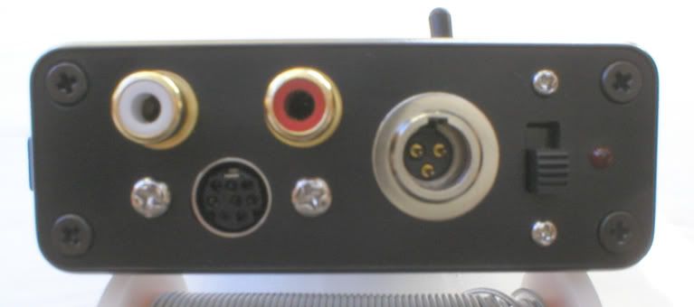
I managed to ghetto-consolize my 2-slot, you can see pics in this thread:

http://www.neo-geo.com/forums/showthread.php?t=123956

However I'm going to try to do a proper consolization of it by installing an on/off switch in the top of the cover, and a power and RGB connector (db9 or din8, I guess I'll go with the db9) in the back-left.

I'll try to use this thread to get some help from you experts ;)

First of all my biggest concern is how to do the proper holes in the case. I have a drill with a small bit for metal, I tried it and managed to make a small hole (around 2-3 mm diameter) with it. I guess I'll have to keep doing holes with it til I make one of the size I want. Would it be possible to "sand" a hole to widen it and make it the exact shape I need?

I'll also have to look for a can of black paint and base for it.

About the on-off switch, I have two (both are double), one has a light and the other has not. Since they will act to connect or disconnect continuous current (5V, and 12V if I connect it as well), will the lighted one work as well? Or are lighted ones only for AC? I'm not sure if there are different kinds for AC and DC.

And now the most important question. I heard that it is possible to make it work with only +5V and not +12V, as long as I take the sound from the headphone connector (notice that I don't have the headphone jack itself in this board, so I'd have to run wires from that connector to my RGB-scart plug). Is this true without any other kind of modification? I have a small multivoltage psu for laptops capable of 5V with enough amps and it would be nice to use it. So instead of using my sc200 psu and needing a din5 plug in the 2-slot, I can just use that smaller psu and install a plug for it, which is like most simple psu's use, like a Genesis or AES one.

Thanks for all :)
 
Last edited:

ttooddddyy

PNG FTW,
Joined
Nov 29, 2001
Posts
8,335
Amano Jacu said:
I heard that it is possible to make it work with only +5V and not +12V, as long as I take the sound from the headphone connector (notice that I don't have the headphone jack itself in this board, so I'd have to run wires from that connector to my RGB-scart plug). Is this true without any other kind of modification?

Simply connect the 5 volts supply to the output of the 7805 5 volt regulator IC.

7805.jpg
 
Last edited:

Amano Jacu

Charles Barkley
Joined
Sep 11, 2001
Posts
8,594
Yeah, that's what I read here:

http://www.neo-geo.com/forums/showthread.php?t=103151

I'll have a look at my board to locate it. So I understand that just by doing that I can get sound without needing +12V. By the way, by doing so do I need to use the headphone connector from sound, or can I get it from the JAMMA harness as well?

BTW, I also added another question about the on/off switch I forgot.
 
Last edited:

ttooddddyy

PNG FTW,
Joined
Nov 29, 2001
Posts
8,335
You will not get sound via jamma as the HA 13001 audio amp will have no 12 volt supply.
 

Amano Jacu

Charles Barkley
Joined
Sep 11, 2001
Posts
8,594
Thanks, I wanted to make sure on that. Anyway it's possibly easier to take the sound from the headphone connector than from the JAMMA one.
 

norton9478

So Many Posts
No Time
For Games.
20 Year Member
Joined
Oct 30, 2003
Posts
34,074
Amano Jacu said:
Thanks, I wanted to make sure on that. Anyway it's possibly easier to take the sound from the headphone connector than from the JAMMA one.

and it's safe for TV.

And it's cleaner.
 

ttooddddyy

PNG FTW,
Joined
Nov 29, 2001
Posts
8,335
Amano Jacu said:
About the on-off switch, I have two (both are double), one has a light and the other has not. Since they will act to connect or disconnect continuous current (5V, and 12V if I connect it as well), will the lighted one work as well? Or are lighted ones only for AC? I'm not sure if there are different kinds for AC and DC.

AC illuminated switches use neon bulbs supplied through a series resistor (typically 100 KOhm with 240 volts), so they are not going to work with a DC supply. It wouldnt be difficult to dismantle the rocker switch and replace the neon with a suitable bulb or LED. There was a thread about this a while ago.
 

Adamaki

Haomaru's Blade Shiner
Joined
Oct 7, 2004
Posts
678
Amano Jacu said:
First of all my biggest concern is how to do the proper holes in the case. I have a drill with a small bit for metal, I tried it and managed to make a small hole (around 2-3 mm diameter) with it. I guess I'll have to keep doing holes with it til I make one of the size I want. Would it be possible to "sand" a hole to widen it and make it the exact shape I need?

And now the most important question. I heard that it is possible to make it work with only +5V and not +12V, as long as I take the sound from the headphone connector (notice that I don't have the headphone jack itself in this board, so I'd have to run wires from that connector to my RGB-scart plug). Is this true without any other kind of modification? I have a small multivoltage psu for laptops capable of 5V with enough amps and it would be nice to use it. So instead of using my sc200 psu and needing a din5 plug in the 2-slot, I can just use that smaller psu and install a plug for it, which is like most simple psu's use, like a Genesis or AES one.

Thanks for all :)

I finished consolising my 2-slot a while ago and I took the sound from the headphone connector. I just soldered two wires on the solder side of the board and threaded them through one of the holes near the memory card reader. I've been meaning to take some photos of the finished console and post them up but it's not quite finished yet (99%, just need a couple of screws)

As for drilling the holes in the case, use a small drill bit to drill a hole then use a dremel tool to make it bigger. That way you can get a perfect round hole that is a snug fit for your connectors. Don't use a big drill bit because you'll just make a hash of the shell like I nearly did!
 

Amano Jacu

Charles Barkley
Joined
Sep 11, 2001
Posts
8,594
OK, I've already done the holes in the metal cover (unfortunately they are pretty bad looking) and soldered all wires to the board. Now I have to paint the cover, then solder the board wires to the connectors and fit the connectors to the cover, and mount the baseplate.

However I have a question. Out of the three pins in the headphone connector, I've figured out which one is ground, but which of the other 2 is Audio left and which is right? Anybody knows or is there a way to find out? It's 50% chance anyway...
 

norton9478

So Many Posts
No Time
For Games.
20 Year Member
Joined
Oct 30, 2003
Posts
34,074
Amano Jacu said:
OK, I've already done the holes in the metal cover (unfortunately they are pretty bad looking) and soldered all wires to the board. Now I have to paint the cover, then solder the board wires to the connectors and fit the connectors to the cover, and mount the baseplate.

However I have a question. Out of the three pins in the headphone connector, I've figured out which one is ground, but which of the other 2 is Audio left and which is right? Anybody knows or is there a way to find out? It's 50% chance anyway...

Go into hardware test mode...

There is a right, left and center chanel test.
 

Amano Jacu

Charles Barkley
Joined
Sep 11, 2001
Posts
8,594
norton9478 said:
Go into hardware test mode...

There is a right, left and center chanel test.

I know, but to do that I already need to have the channels wired. What I meant is some way to do so before wiring them, so I don't have to rewire them if I wire them the wrong way. It's 50% chance anyway.
 

Yodd

Iori's Flame
20 Year Member
Joined
Feb 7, 2002
Posts
8,220
This is a pic I took a couple years ago when I did my first 2 slot console.

boardmod.jpg
 

norton9478

So Many Posts
No Time
For Games.
20 Year Member
Joined
Oct 30, 2003
Posts
34,074
Amano Jacu said:
I know, but to do that I already need to have the channels wired. What I meant is some way to do so before wiring them, so I don't have to rewire them if I wire them the wrong way. It's 50% chance anyway.

If the jacks are still present, you can use a multimeter with continutity test and a headphone->RCA cable.

white is left, Red is Right
 

Amano Jacu

Charles Barkley
Joined
Sep 11, 2001
Posts
8,594
The jacks are not present, that's why I was asking.

Thanks for the pic Gill, that's what I needed :)
 

Adamaki

Haomaru's Blade Shiner
Joined
Oct 7, 2004
Posts
678
I just took a chance and soldered the wires on then did the left / right channel test in test mode. Luckily I got it right. If I got it wrong all I'd have to do is swap the wires round - easy!
 

Amano Jacu

Charles Barkley
Joined
Sep 11, 2001
Posts
8,594
OK, I just finished consolizing it, all works OK with only 5V :buttrock:
However, even with the headphone volume all the way up in the mobo, I have to turn up a bit more than normal the volume in my TV or stereo, but that's no problem.
There are still some final touches left, but it is already 100% functional:


Thanks to everybody that helped ;)

EDIT: new pics in another post
 
Last edited:

Yodd

Iori's Flame
20 Year Member
Joined
Feb 7, 2002
Posts
8,220
Looking good!

You should upload some pics to SGR when you have a chance.
 

Amano Jacu

Charles Barkley
Joined
Sep 11, 2001
Posts
8,594
Yeah, I've wanted to start an account at the sgr for a while, I have to sit in front of my computer and look for all the pics I have and then upload them. About the 2-slot, it is not 100% finished because I have some trouble with the back of the unit (that's why it isn't pictured ;) ), I'll do more pics if I manage to solve it, if not I'll just leave it like that.
I'll possibly do it in the next days.
 

Adamaki

Haomaru's Blade Shiner
Joined
Oct 7, 2004
Posts
678
Nice work Amano. Mine's pretty much the same and I'm going to upload some pics as soon as I finish off the back of the unit. Just need a few screws to secure the din sockets to the shell. I used a piece of acrylic for the base as well. Isn't yours a bit flexible as it's quite thin though? I used 1/4 inch to make sure there's no flexibility in it.
 

Amano Jacu

Charles Barkley
Joined
Sep 11, 2001
Posts
8,594
Yeah, mine is a little bit too thin, there's some flexibility there... I think it was 3 mm thick and I should have done a bit more. Anyway it still works quite well, and it will be better once I install the central "legs" in the cart slot.
And also I'm having trouble with the back... The power connector is so small the holes for screws on it are really thin and there's no screw thin enough for them. The db9 has regular 3 mm holes but I couldn't make holes that size, I'll have to buy a 3 mm bit drill.
 

Adamaki

Haomaru's Blade Shiner
Joined
Oct 7, 2004
Posts
678
I wouldn't even try to put a game in the slot without those central legs. It would bend the board a lot! :eek:

I'll try and remember to take some pics of mine tonight so we can compare.

What power connector did you use? I used the SC200 so it was a 5 pin din socket. I had trouble getting small diameter screws as well. I think they're only used for electrical applications. I ended up getting mine from our workshop at uni. That guy's got everything in there!
 

ttooddddyy

PNG FTW,
Joined
Nov 29, 2001
Posts
8,335
Adamaki said:
What power connector did you use? I used the SC200 so it was a 5 pin din socket.

The XLR is a far sturdier connector for psu hook up imho, especially for multi slots.

s25k.jpg
 

Amano Jacu

Charles Barkley
Joined
Sep 11, 2001
Posts
8,594
Well, since I only need 5V, my psu (you can see in it in the pic) has a very small plug, like the one AES or Megadrive uses. The connector in the 2-slot just has a central pin (hooked to 5V) and the outside of it is just the ground, and as I said the "support holes" are very small, in my local "drugstore" they don't have screws that small, tomorrow I'll go to the electronics one to see what I can find.

Yeah, I know without the central legs putting carts is a bit of a hassle, but I can't use the same kind of "columns" I used for the outer legs because the central ones need to be taller, because of the cart slot. Tomorrow I'll look for something better.
 

John_Smith

B. Jenet's Firstmate
Joined
Jun 9, 2003
Posts
400
ttooddddyy said:
The XLR is a far sturdier connector for psu hook up imho, especially for multi slots.

s25k.jpg

Ah yeah, werd! Real sturdy, quite compact and enough pins to support all necessary voltages for a supergun when using the shell/casing/hood as GND (just a recommendation, pin-out is up to you peeps!!). :D Ya can get a 4 pin version too.

I used the male version on my SG (& all my other gadgets that relate to this crazy hobby for that matter) as they're a little less obtrusive than the chunky square metal part with the clip button, oh and a little cheaper too!!

_S-Gun_07.jpg


But yeah, if you only need GND and VCC then why not use a little Genesis/SNES style plug...

Good work Amano, very tidy!! :buttrock:
 

Amano Jacu

Charles Barkley
Joined
Sep 11, 2001
Posts
8,594
OK, actually I just finished all the missing details I mentioned today. I've painted it again (still there are some zones not 100% OK), replaced the feet for something much better, and added more columns for a total of 11, including 2 at the sides of the central cart slot so now inserting carts is not a problem. I've also fixed with thin screws (2mm) the 2 back connectors. Unfortunately their holes are not exactly the same size/shape of the connectors, and the db9 is not perfectly parallel to the ground, but oh well, I had a lot of trouble drilling the cover so I think it's good enough.

New and better pics:

2slotc2-1.jpg


2slotc2-2.jpg


2slotc2-3.jpg


2slotc2-4.jpg


2slotc2-5.jpg


2slotc2-6.jpg
 
Top