Autofire Circuit

SephirothFF

Quiz Detective
Joined
Jul 18, 2004
Posts
80
After having searched the forums for information on this topic I have only found fragments from these two threads:

http://www.neo-geo.com/forums/showthread.php?t=20498

http://www.neo-geo.com/forums/showthread.php?t=113212

I also tried to use information from this site:

http://www2.asw.cz/~kubecj/atjoy.htm

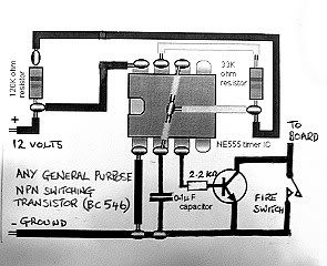
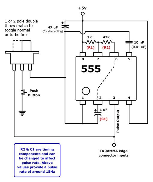
but unfortunately I can't seem to work it out. I have bought an ne555 timer IC, 1 0.42nF capacitor, 1 100nF capacitor, 2 10K resistors and a 2-position switch (to turn autofire on/off). In the schematic that was drawn in the 113212 neo thread the IC pictured there is exactly the same as the one that I have but the ingredients needed to make the circuit seem to be different to those listed on the site directly above this paragraph. I am also not entirely sure about where to get +5 volts from on my supergun as it has that crappy arcade heaven wiring and how to implement the switch feature.

If anyone could possibly take the time to explain the wiring of this simple circuit for me then I would be eternally grateful.
 

ttooddddyy

PNG FTW,
Joined
Nov 29, 2001
Posts
8,335
autofire.jpg


I drew that diagram, the values of the components was just an educated guess, its not critical as long as the NE 555 oscillates at more than a few Hz. I measured the frequency at about 100 Hz. Thats like hitting the fire button 100 times/sec !

You can run the NE 555 from either 5 or 12 volts.
The collector of the switching transistor (where you see "TO BOARD" connects to your fire button switch, the other side of the switch is grounded.

To switch the feature on and off just put a switch on the 5 or 12 volt supply to the NE 555.
 

toodles

Zero's Secretary
Joined
Jul 14, 2005
Posts
157
Assuming the chip was turned on and powered, wouldn't that make the button autofire when the button was NOT pressed, and act like it was held down when the button was pressed? The pushbutton and the transistor are in parallel; shouldn't they be in series?
 

ttooddddyy

PNG FTW,
Joined
Nov 29, 2001
Posts
8,335
toodles said:
Assuming the chip was turned on and powered, wouldn't that make the button autofire when the button was NOT pressed, and act like it was held down when the button was pressed? The pushbutton and the transistor are in parallel; shouldn't they be in series?


You are quite correct, my bad. I actually wired it correctly as it works well in one of my cabs.
 

SephirothFF

Quiz Detective
Joined
Jul 18, 2004
Posts
80
Ok, anyone who knows anything about electronics PLEEEASE help me out because after scratching my head for a day and a half I still cannot figure out the problem with my circuit. Oh and the polarities are fine on the cap and LED - I checked them.

ne555circuit.jpg
 

SephirothFF

Quiz Detective
Joined
Jul 18, 2004
Posts
80
ok I fixed the problem. Turns out three points on the chip itself weren't properly soldered to the track. The solder was on the chip leg, just not connected to the track.

Anyway so I got the led blinking all that's left to do now is change the capacitor because 2hz is a little slow for autofire.

One final question for toodles or anyone about:

at the moment, the minute I touch the fire button to pin 3 on the ne555 chip it starts autofiring and as you said in an earlier post if I hold that button down then it acts like the button is pressed down. How exactly would I rectify this?

Thanks.
 

toodles

Zero's Secretary
Joined
Jul 14, 2005
Posts
157
Take an eraser and erase the pushbutton piece of his schematic entirely. Where it says 'to jamma', connect to one leg of the pushbutton. The other leg of the push button goes to the button line on the jamma. (there are a couple of other places it could go, but there is the easiest to explain without making a picture).

Id recommend about 15hz. Almost every game checks the state of the button on vsync, is 30Hz on older games and 60Hz on newer games. 15Hz is plenty fast, and if you move it up to faster than 1/2 the refresh rate of the game, then it will see the button pressed two frames in a row, and the game will act like it was held down, defeating the purpose of have turbo.
 

SephirothFF

Quiz Detective
Joined
Jul 18, 2004
Posts
80
hmmm. Not entirely sure what you mean when you say to one leg...

My button has a solder point for the button and a solder point for its ground which is the common ground for the board. Which wire from where do I connect to the output pin on the ne555?
 

SpamYouToDeath

I asked for a, Custom Rank and, Learned My Lesson.
15 Year Member
Joined
Oct 3, 2005
Posts
6,059
The output goes to the JAMMA edge connector pin, I believe.
 

toodles

Zero's Secretary
Joined
Jul 14, 2005
Posts
157
the transister. The transister acts like a gate. When the middle pin gets electricity (in this case, the rythmic pulses from the 555), it allows current to flow through the other two legs (opening the gate). When there is no electricity to the middle leg, the gate is closed.

When the game is on, there is a buildup of electricity on the button pin of the jamma board. As long as that electricity buildup is there, the game knows the button is not pressed. When the pressure is let loose, by connecting it to ground, the game knows the button is pressed. If you wire up that schematic without any button, the 555 will spit out rythmic pulses of electricity, causing the transister gate to open and close very quickly. When its closed, the pressure on the button pin of the jamma board stays high, because there is no where for the electricity to go. Game thinks button is not pressed. When the gate is open, the pressure drops because all of the electricity is flowing through the gate to ground. Game thinks button is pressed. Because it opens and closes very quickly, viola, turbo.

The only problem is that it will ALWAYS be turbo'ing. You don't want that. You want it to be turbo only when the button is pressed. So, put the pushbutton before the jamma pin. If the button is not pressed, then the electricity on the jamma pin will always be high because there is nowhere for the electricity to go. When the button is pressed, the electricity will flow to the transister gate, and be high when the gate is closed, and low when the gate is open. Bingo, turbo.

If you're putting this in your namco, things will get a bit hard. All of the buttons have ground on one pin. You can't have that for this, because you need it to go through the transister gate before going to ground. Cut a trace or do some tricky rewiring first.
 

ttooddddyy

PNG FTW,
Joined
Nov 29, 2001
Posts
8,335
The easiest way to connect this is to have the existing fire button switch the 12 volts supply to the 555 circuit.
Then connect the collector of the switching transistor to the game boards fire button input.
 

SephirothFF

Quiz Detective
Joined
Jul 18, 2004
Posts
80
ok so what component do I use the fire button to switch on the +5V? and where do I put the switch now to turn on/off autofire? Toody said something about a dangling 2 way switch?
 

ttooddddyy

PNG FTW,
Joined
Nov 29, 2001
Posts
8,335
SephirothFF said:
ok so what component do I use the fire button to switch on the +5V? and where do I put the switch now to turn on/off autofire? Toody said something about a dangling 2 way switch?


The fire button is used to switch the 5 volt supply to the NE555 circuit.

The collector of the switching transistor is connected to the fire button input to the game board.
 

SephirothFF

Quiz Detective
Joined
Jul 18, 2004
Posts
80
If you're putting this in your namco, things will get a bit hard. All of the buttons have ground on one pin. You can't have that for this, because you need it to go through the transister gate before going to ground. Cut a trace or do some tricky rewiring first.

Erm how do I go about cutting a trace?
 

SephirothFF

Quiz Detective
Joined
Jul 18, 2004
Posts
80
ttooddddyy said:
The fire button is used to switch the 5 volt supply to the NE555 circuit.

The collector of the switching transistor is connected to the fire button input to the game board.

when you say the fire button is used to switch the 5 volt supply to the circuit how exactly do I wire the button to the 5 volt wire? I tried connecting one end of the 5v wire to the button pin and one to the button's ground but pushing the button didn't activate the circuit. I think the problem is becuse the fire button on my joystick PCB has a common ground which it shares with all the other pins...
 

ttooddddyy

PNG FTW,
Joined
Nov 29, 2001
Posts
8,335
isolate the fire button switch then connect one side to the 5 volts and the other to supply the N555 circuit.

They way my diagram is wired earlier in this thread is for a seperate (additional) autofire button, where the 5/12 volts is switched via this button.

Remember in that application the switch is shown in the wrong position, it should be switching the supply not accross the existing fire button switch.
 
Last edited:

SephirothFF

Quiz Detective
Joined
Jul 18, 2004
Posts
80
Ok seriously last question. What kind of switch do I need to switch between normal fire and autofire?
 

John_Smith

B. Jenet's Firstmate
Joined
Jun 9, 2003
Posts
400
ttooddddyy said:
isolate the fire button switch then connect one side to the 5 volts and the other to supply the N555 circuit.

They way my diagram is wired earlier in this thread is for a seperate (additional) autofire button, where the 5/12 volts is switched via this button.

Remember in that application the switch is shown in the wrong position, it should be switching the supply not accross the existing fire button switch.

Hey there Toddy!! I've previously made up a few turbo fire circuits based on different chips like the 4049 6 gate hex inverter/buffer and the LM3909 flasher, but recently settled on a little 555 timer chip which has been great, but my circuit is quite a bit different than the one you drew up. I haven't used any additional external Transistor and my other passive components vary in number and value too. I drew up a nice circuit layout in Flash for ya to look at and tell me if there's anything you think could use some mods.

555TurboFireCircuit.jpg


The reason I ask this is I've heard that implementing an open collector either on chip or made from external components is a good idea rather than feeding the high portion of the duty cycle through to the edge connector. Is it dangerous for the PCB to have a high signal sent back at the input pins on the edge connector? Should it really operate as open, GND, open, GND and so on rather than Vcc, GND, Vcc, GND?

Or am I just confused!! :loco:

Oh yeah, and also, I've left Vcc connected full time and taken advantage of the grounding action of the typical controller pushbuttons to complete the circuit and activate the 555 rather than switching the supply voltage. I thought this was WAAAYYYY more convenient to hook up than the other way around. ;)
 
Last edited:

ttooddddyy

PNG FTW,
Joined
Nov 29, 2001
Posts
8,335
John_Smith said:
I haven't used any additional external Transistor and my other passive components vary in number and value too. I drew up a nice circuit layout in Flash for ya to look at and tell me if there's anything you think could use some mods.

That looks fine John, and no need to isolate the fire button switch.
Its an all round better implementation for what we are trying to achieve here.
Yes the diagram is a little more proff than mine :chimp:

Is it dangerous for the PCB to have a high signal sent back at the input pins on the edge connector? Should it really operate as open, GND, open, GND and so on rather than Vcc, GND, Vcc, GND?

It should, you are pulling down a voltage supplied via the resistor array pd circuit to get a low logic level on the input inverters/buffers.
Using the switching transistor achieves the same on this score.

Oh yeah, and also, I've left Vcc connected full time and taken advantage of the grounding action of the typical controller pushbuttons to complete the circuit and activate the 555 rather than switching the supply voltage. I thought this was WAAAYYYY more convenient to hook up than the other way around. ;)

That makes switching the circuit in and out a whole lot easier- nice work John Smith :)
 

John_Smith

B. Jenet's Firstmate
Joined
Jun 9, 2003
Posts
400
Dah jeez...shucks! Thanks for the kind words and clarification on my concerns Toddy!!! ;) You're always good for the odd word of wisdom ol boy!

Cheers!
JS
 

SephirothFF

Quiz Detective
Joined
Jul 18, 2004
Posts
80
Hi everyone! Thanks so much for all your help before. I just got back to trying to figure out this autofire circuit and I'm still slightly stuck.

I did what toody suggested and have wired the fire button to the 5v input on the circuit so when I press the button tada the led blinks. I then tried using the transistor but since I'm not entirely sure how it works I was a little stumped when it didn't work.

I had the pulse coming off pin 3 on the NEC555 on the base pin (middle), GND connected to the emitter (left pin) and the collector connected to the jamma board as suggested. However, when I did that, I got no output when pressing the button at all. When I disconnect ground however autofire seems to work.

I'm a bit confused as to the purpose of the transistor however since what I really wanted was to use a switch to turn the feature on and off. The closest I have gotten so far is to use a SPDT switch with the same setup as the transistor. Although autofire seems to work, throwing the switch the other way appears to do nothing at all...
 

SephirothFF

Quiz Detective
Joined
Jul 18, 2004
Posts
80
Never mind. I thought about the circuit some more and finally got the config on the SPDT switch correct. GND connects to the left pin, middle pin connects to pin 1 on the button, right pin connects to the pulse output on the circuit. The remaining pin on the button connects to jamma - so we are effectively lifting the ground from the button onto the switch.
Anyway - thanks to all that helped out especially toody and toodles. I think this thread can finally be put to rest.
 
Top