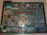
Which PCB REVISION AES do I have? Is it gen 1?

Tengugurl

Cheng's Errand Boy
Joined
Feb 9, 2017
Posts
111
Hello!
Just bought a junk AES pcb set and I am thinking they are 1st gens but, I am not too sure.

Can you tell?

Also, I have seen gen 1 revisions have a secondary daughter pcb in the right most section of the pcb.

Called a neo power? Wonder if I am missing this?
I have a 3-6 so this is all new to me lol
Getting up to speed with this model pcb.

guess I’d also need to know if I have a 5v+ or 9v+ model?

Per here:

Just curious if any neo geo gurus could help me out while I wait for them to arrive
 

Tengugurl

Cheng's Errand Boy
Joined
Feb 9, 2017
Posts
111
Pic of pcb
 

Attachments

  • 4E18213B-E76A-490A-8227-956BD46E455D.jpeg
    4E18213B-E76A-490A-8227-956BD46E455D.jpeg
    537.4 KB · Views: 31

maki

Edo Express Delivery Guy
Joined
Jan 1, 2022
Posts
340
Hi :)

FWIW, you can tell the PCB revision just by the slot and it's components.
But since you have it open, on the right side of the PCB it says the revision/model.
Yours should say "NEO-AES", thats the first PCB model, however, they were produced with or without certain daughterboads.

By the pic, yours had the PLL daughterboard, just like mine, easy to tel because the master clock crystal is not on the PCB.

It won't work at all without either the daughter PCB (Video PLL) or by putting the 24.167829MHz crystal directly on the main PCB.

The purpose of the Video PLL is to stabilise the Composite picture, at the expense of the masterclock stability and al that comes with it, like RGB will be worse with the daughterboard.


FYI, these first gen chipsets create a terrible sync signal, lots of modern LCDs will have problems with it, picture won't be stable.
If thats the case, don't be like me and try to repair it for weeks, get a good CRT or an OSSC.

Edit:
here is my thread about fixing my 1st gen model AES AEC:

There is some discussion and finding about the Video PLL and other stuff about this revision.
 

Tengugurl

Cheng's Errand Boy
Joined
Feb 9, 2017
Posts
111
It says neo geo AES from what I can see. (Still waiting for it to arrive by mail)

Oh dang, yeah I bought a set of these and I don’t have the daughter boards.

Oh nice, good to know, I’d plan on using a CRT anyway.

Going to have a look at your post.

Darn, seems I am in for a bit of work because I am missing that daughter board.
I wonder if there is a way to make my own version of the daughter board and or making a 24.167829MHz crystal?
 

BIG BEAR

SHOCKbox Developer,
20 Year Member
Joined
Dec 14, 2001
Posts
8,280
You don't have to make a daughterboard,just get the 24MHz crystal and install it on the main board.
You should be able to pick them up cheap.
Make sure your 5v 3A supply has a negative polarity or you switch it to that.. I have a 3rd party 3v 2500ma(2.5a) that I am currently using now.
BB
 
Last edited:

Tengugurl

Cheng's Errand Boy
Joined
Feb 9, 2017
Posts
111
Oh nice! @BIG BEAR made my night to hear I don’t need the Daughter board.

I had a look to see if someone has done it before in a previous post but I haven’t seen a link out there.

When you say installing it, do you know which connection points I’d need to go to?
I am guessing via a pic I found

Thanks so much btw all! ❤️
I am super excited to have an AES that I can resurrect so any guidance or links are super appreciated, thanks :)

If there isn’t a guide on this, I’d be happy to help in documenting. Haha if I can get up to speed lol
 

Attachments

  • 26103224-B84C-49C4-A264-0C1EA8439CB1.jpeg
    26103224-B84C-49C4-A264-0C1EA8439CB1.jpeg
    1.2 MB · Views: 10

maki

Edo Express Delivery Guy
Joined
Jan 1, 2022
Posts
340
you can get 24.000MHz crystals for cheap on ebay, the AES uses a 24.167829MHz crystal to improve the refresh rate, Dual Frequency Oscillator solutiopns aim for 24.3ish

but yeah forget about the daughterboard, causes more trouble than it fixes, its really just for composite, so you have an RGBs capable CRT?

the last pic you shared if from a AES3-5 or AES3-6
 

Tengugurl

Cheng's Errand Boy
Joined
Feb 9, 2017
Posts
111
@maki I do have a trinitron I RGB scart modded and a pvm so I am fortunate to be set in that area.

Ahh darn in regards to pulling a pic of one installed on a different pcb. Wish I could find an example of a Rev 1 that has one installed. (Location/pic wise)

On that note , do you know where or how I’d install the crystal? I am still learning a lot but happy to research more and put things together as I go.

Would this be a good crystal to buy? *pic attached

I couldn’t find one with the 24.167829MHz
I see the MVS uses 24mhz and I am wondering if I could go up to 25? Or less is better?

Ps so appreciate your guidance, means a lot to me ❤️

If I understand correctly, the pcb could be powered by a 5v 3a center negative PSU, and I’d need to install a crystal (somewhere to help with sync issues) and theoretically I could have it up and running (best case scenario haha if ICs aren’t fried etc…)

If so, that would be exciting :)
 

Attachments

  • 2E9F3F35-F392-41AA-A24E-AA676103185B.jpeg
    2E9F3F35-F392-41AA-A24E-AA676103185B.jpeg
    518.8 KB · Views: 1

Neo Alec

Warrior of the Innanet
20 Year Member
Joined
Dec 7, 2000
Posts
12,650
I couldn’t find one with the 24.167829MHz
I see the MVS uses 24mhz and I am wondering if I could go up to 25? Or less is better?
:)
Per this old post from Xian Xi, older AES boards like yours use a 24 MHz crystal, while the 3-3 and on used 24.16 MHz.


This kind of makes me want to switch out the crystal on my 3-4 board to a 24 MHz crystal so that it runs at the original rate -- the rate used by the first AESes and all MVSes.
 

maki

Edo Express Delivery Guy
Joined
Jan 1, 2022
Posts
340
the 24/24.169/24.3Mhz crystal goes in there, it really just two solder point

using a faster crystal than the original 24Mhz MVS raises the refresh rate and thus increases compatibility a bit with CRTs, with 24Mhz its closer to 59Hz instead of 60Hz, but if your CRT displays the lower refresh rate, its fine as well

Edit:
24Mhz crsytals are plenty on ebay, if you can, look for one with 18-22pF, most will be okay though

Have you received the AES already?

Screen Shot 2022-03-01 at 8.05.43 am.png
 
Last edited:

maki

Edo Express Delivery Guy
Joined
Jan 1, 2022
Posts
340
I've just removed the daughterboard from my 1st model, really no point in keeping it if all I'm using is RGB, red arrow on top, ignore the "Text"

PXL_20220301_121322858.jpg
 

Tengugurl

Cheng's Errand Boy
Joined
Feb 9, 2017
Posts
111
You all are so amazing! Thank you ❤️
Not yet but I am so going to be ready when it arrives.
I am going to clean it up, recap it, put that crystal in and be set to game.

So freaking excited!! All thanks to your help :)
Major kudos to everyone ++++++ I love this forum
 

Tengugurl

Cheng's Errand Boy
Joined
Feb 9, 2017
Posts
111
just got my PCB :)
Looks like I am missing a few things

1) I am missing a chip at 43256 (upper one)
A.From the wiki https://wiki.neogeodev.org/index.php?title=RAM_chip
It seems like it’s a work RAM IC (upper?)
B. Would this work as a replacement?
https://www.ebay.com/itm/Ci-CXK5825...2349624.m46890.l49286&mkrid=711-127632-2357-0

2) I am missing an upper and lower 43256 near the BIOs area similar ICs.
A. Sony CXK58256 120ns
Work, Backup and Video RAM
B. Are there any differences between an up and lower 43256 chip?


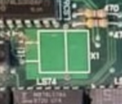
3) I am missing a LS74
A. Guess it’s a banking chip
B. Saw a pic of another online and it said
mb74ls74a can’t find a replacement one online, are there specs you’d recommend looking up for a comparable IC?

Besides these things missing, looks like it needs a good scrubbing and some solder reflow work.
Hoping I can get it up and running :)

Thanks for any help you can provide on these missing chips.

I’ll start a new thread I am sure once I can pop in a diagnostic bios chip in there and see if I can get it to boot.

Oh sorry! Last question (this post lol )
Anyone in the forum who’s a good contact to buy Unibios and or diagnostic bios from?

I remember buying from JNX a few years back but figured I’d ask as I haven’t been on this site for a few years

Thanks
 

Attachments

  • 30FEE24B-1E82-4F7E-8FC7-4FA53B017852.jpeg
    30FEE24B-1E82-4F7E-8FC7-4FA53B017852.jpeg
    1.8 MB · Views: 13
  • D364DEA2-AB35-4CAD-B0F4-EF258A02CDBD.jpeg
    D364DEA2-AB35-4CAD-B0F4-EF258A02CDBD.jpeg
    1.5 MB · Views: 11
  • 2EDB0267-1156-485E-89EF-0394C8194755.jpeg
    2EDB0267-1156-485E-89EF-0394C8194755.jpeg
    1.9 MB · Views: 11

BIG BEAR

SHOCKbox Developer,
20 Year Member
Joined
Dec 14, 2001
Posts
8,280
just got my PCB :)
Looks like I am missing a few things

1) I am missing a chip at 43256 (upper one)
A.From the wiki https://wiki.neogeodev.org/index.php?title=RAM_chip
It seems like it’s a work RAM IC (upper?)
B. Would this work as a replacement?
https://www.ebay.com/itm/Ci-CXK5825...2349624.m46890.l49286&mkrid=711-127632-2357-0

2) I am missing an upper and lower 43256 near the BIOs area similar ICs.
A. Sony CXK58256 120ns
Work, Backup and Video RAM
B. Are there any differences between an up and lower 43256 chip?


3) I am missing a LS74
A. Guess it’s a banking chip
B. Saw a pic of another online and it said
mb74ls74a can’t find a replacement one online, are there specs you’d recommend looking up for a comparable IC?

Besides these things missing, looks like it needs a good scrubbing and some solder reflow work.
Hoping I can get it up and running :)

Thanks for any help you can provide on these missing chips.

I’ll start a new thread I am sure once I can pop in a diagnostic bios chip in there and see if I can get it to boot.

Oh sorry! Last question (this post lol )
Anyone in the forum who’s a good contact to buy Unibios and or diagnostic bios from?

I remember buying from JNX a few years back but figured I’d ask as I haven’t been on this site for a few years

Thanks
You have the one video ram missing,the ls74 and the reset button from what I
Can see.......
The work rams are near the bios chip and they are interchangeable with the video rams.
The good thing is,is that it looks like bios wasn't disturbed so you don't have to worry about a
whole lot of tracks being broke.
In order to use the uni-bios and the diagnostic bios you're going to have to remove the original bios cleanly and place a 40 pin socket in it's place. Are you up for that?
I could probably supply you with all the parts you need but you have to get that socket on the board.
BB
 

maki

Edo Express Delivery Guy
Joined
Jan 1, 2022
Posts
340
the missing logic IC "LS74" is originally a HD74LS74AP, you can get them on ebay, mouser, digikey etc.
the are cheap, but a single one will be more expensive than 10 of them per piece

that board is also missing the reset button

how good are your soldering skills?

reason I'm asking, if that board was a donor, it might have more issues than the missing parts

Edit:
the creator of JNX is hanging out here as well, username "Xian Xi"
I'm assuming you're in the the US or Canada

Edit 2:
there is a missing 100p cap next to where the crystal needs to go, parts of the legs are still there
 
Last edited:

Tengugurl

Cheng's Errand Boy
Joined
Feb 9, 2017
Posts
111
Oh dang! You are right! I am missing a reset button @_@ -> gotta add that to the list too lol (updated got a square tactile switch replacement off eBay)

@BIG BEAR thank you! Yup I am decent at soldering and will be able to put a socket in on the bios but will need a pair of diagnostic bios and Unibios (unless I can find my old set from a few years back)

Got a socket ready to go, watched a lot of videos to make sure I don’t do the Pry and cry method. (Please neo geo gods don’t forsake me)

Oh also, it seems there is no difference in upper and lower rams in the missing 43256 chips.
Just need to find a comparable IC.
Any model number suggestions besides Sony CXK58256?
(Update found a great link https://www.neo-geo.com/forums/index.php?threads/okay-mvs-board-replacement-parts.21279/
@maki I am not too bad at soldering, if it was a donor board I enjoy learning and seeing if I can resurrect it. (Fingers crossed)

I bought this LS74 replacement last night. Hope it’s the right kind https://www.ebay.com/itm/MB74LS74A-...349624.m46890.l49286&mkrid=1185-127638-7840-0

If not, I am cool finding the one for one part HD74LS74AP. (I am not sure I read a wiki page wrong but dang, it’s missing the P after the model number which is concerning. (Haha I am just too ambitious to have a working AES)

Todays the day, going to clean this bad boy up and inspect for damage. :)
 
Last edited:

Neo Alec

Warrior of the Innanet
20 Year Member
Joined
Dec 7, 2000
Posts
12,650
If you're planning to recap it, then you must be pretty decent at soldering.
 

maki

Edo Express Delivery Guy
Joined
Jan 1, 2022
Posts
340
@maki I am not too bad at soldering, if it was a donor board I enjoy learning and seeing if I can resurrect it. (Fingers crossed)
these PCBs are really fragile, traces will lift off just by looking at them too hard
the PCB will delaminate if temps are higher than 320Cish, resulting in whitish spots/areas, the epoxy that holds the traces on the PCB is so old, too hot and its gone, thats why traces are lifted so easily
very common to have rotten traces, and I have trust issues with all vias on these PCBs

if you're not 100% certain you're able to do that, I'd leave that to someone who is, lots of damage can be done with a soldering iron, causes much bigger problems than the original problems, thats the reason people recommend not to desolder the BIOS, but cut the legs off and carefully removing each left over leg

I bought this LS74 replacement last night. Hope it’s the right kind
I think it will work, however this one is expensive with shipping from Spain, only makes sense if you're in Spain

if you happen to be in Germany (I am), this is a better deal IMO
 

Tengugurl

Cheng's Errand Boy
Joined
Feb 9, 2017
Posts
111
*confident deep breath :) lol
I am positive that I won’t cause damage. The reason I bought this project PCB was for fun and to undo a mistake I made 3 years ago.

Story time lol as I reflect back on this often and feel it’s good to acknowledge that growth can come from determination and ultimately the worst case scenarios.

I bought a perfect working neo geo from Japan once upon a time and decided it was smart to try and remove the bios with a hot air desoldering iron that I had zero experience with on max settings. Needless to say , I melted the PCB so badly it had a permanent bend in it. Then decided a flat bladed screw driver was ideal to pry the bios up while I further melted the pcb.

I spent hours researching pinouts from the bios to the cart slot to the Neo ICs and made jumper wires to each respective spot throughout the board effectively retracing the pcb where the sink hole I created had been impacted. I got so into fixing my mistake that I learned how to read address lines and interpret stuck on high etc.

I got the AES working once more thanks to the lovely community here (documentation and helpfulness) and my determination towards learning from my mistake.

This pcb will be a chance for me to prove to myself that I can touch one of these without breaking it as silly as it seems. Glutton for punishment perhaps but I really want to refine my craft/hobby and continue to push to be as good or on the level of all the great gurus out here on this forum.

Sorry for my life story just sharing as you are so right. These things are delicate and I’d wish I left things be 3 years ago but, I wouldn’t be half as good as I am today without that reminder of how close I got to destroying something I so dearly love.

I like to say I am decent at soldering to remain humble as anyone with a soldering iron knows, you are 2 degrees temp wise and 2 seconds too long on one spot from destroying something.

On a shorter note lol (promise I won’t reply that long again)
Thanks for the suggestion on the LS74 :)
 

maki

Edo Express Delivery Guy
Joined
Jan 1, 2022
Posts
340
sounds like you made your experience with AES PCBs :)

as you saw, seemingly simple things like "desolder a 40 pin IC" end up in in lots of rework/lifted traces/hours of following traces/reading schematics

I reckon you'll be fine :)

its safer to clip the legs of the BIOS :)
 

slugger_dan

Crazed MVS Addict
10 Year Member
Joined
Jul 15, 2008
Posts
134
Lots of stories on this forum about damaged AES boards from attempted BIOS mods. The ground pins are the worst to get solder out from. I was doing enough DIP desoldering to buy a vacuum desoldering station which makes short work of it. It's quick, easy and less risk of damage but you'd have to do enough of these mods and repairs to justify buying the station in the first place.
 

Tengugurl

Cheng's Errand Boy
Joined
Feb 9, 2017
Posts
111
Omg so true @slugger_dan gerdan I love my hakko desoldering station

@maki I am so going to do the clip approach. Haha ugh yes definitely hard knock way of learning but happy I could learn/ grow from it.
 

maki

Edo Express Delivery Guy
Joined
Jan 1, 2022
Posts
340
Lots of stories on this forum about damaged AES boards from attempted BIOS mods. The ground pins are the worst to get solder out from. I was doing enough DIP desoldering to buy a vacuum desoldering station which makes short work of it. It's quick, easy and less risk of damage but you'd have to do enough of these mods and repairs to justify buying the station in the first place.
I have a desoldering station, not using it on AES anymore, its not really temp controlled (like my soldering iron) and while fast, its easy to do damage

Now I use a tiny soldering tip, het each leg individually without touching the PCB, and a manual desoldering pump, doesn't take much longer but much safer

also, I wish I just got the the desoldering gun, not a full station, lots of space wasted for the amount of times I use it

I am so going to do the clip approach. Haha ugh yes definitely hard knock way of learning but happy I could learn/ grow from it.

clipping the legs is safest IMO if you're not used to it
 
Top