Yeah ...So I opened up the back of my cab and snapped some more pics: ...
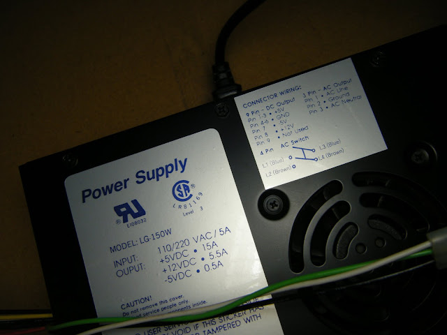
Pic #1: Black Power Supply #1 (Up Close).
Obs 1: The Big sticker has the Wattage and Voltage Ratings. That's the same as the HAPP PSUs above.
Obs 2: The Little sticker is the pinout for the 9 pin molex connector. It tells you Voltage wire or Ground wire the maker put in each Molex housing number. It also has the wiring diagram for your on/off switch. That's the wires in the 4 pin molex connector.
Obs 3. Those three wires running across the PSU in the three pin molex connector provide power to the ISOLATION TRANSFORMER. And the ISO-TRANS provides power to the monitor.
-----
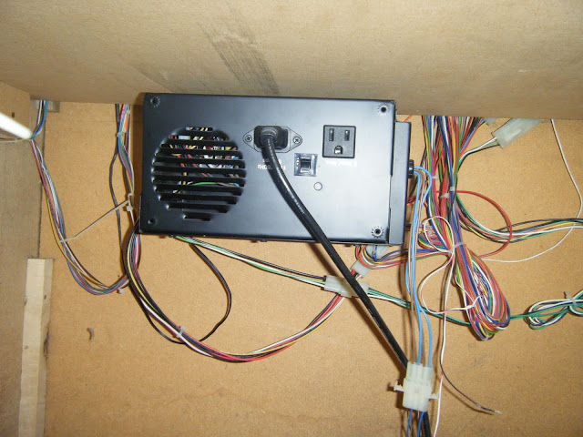
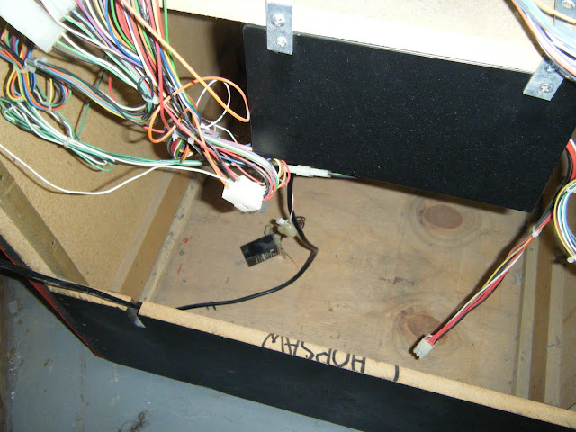
Pic# 2 Cab. Drawer.
Obs 1: On the bottom left hand side of pic., the big black box is the ISO-TRANS.
Obs 2: And also on the same side, bib black box just above it is a second power supply.

-----
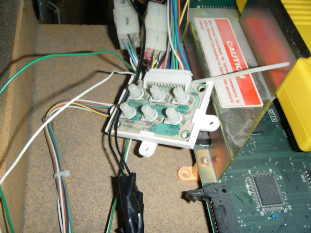
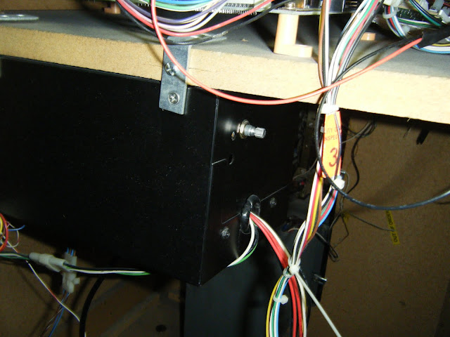
Pic#3 Black Power Supply #2 (Up Close).
Obs 1: The knob on the PSU is the Voltage adjust knob. Be careful when you adjust the Voltage up--chips fry at 5.25V.
Obs 2: Looks like the 3 pin molex connector for the ISO-TRANS is connected to something. I presume it's the ISO-TRANSFORMER.
Obs 3: The 4 pin molex connectors (with the Blue and Brown wires in it) in the background has the on/off switch wires in it. And, it is probably connected to the on/off switch.
-----
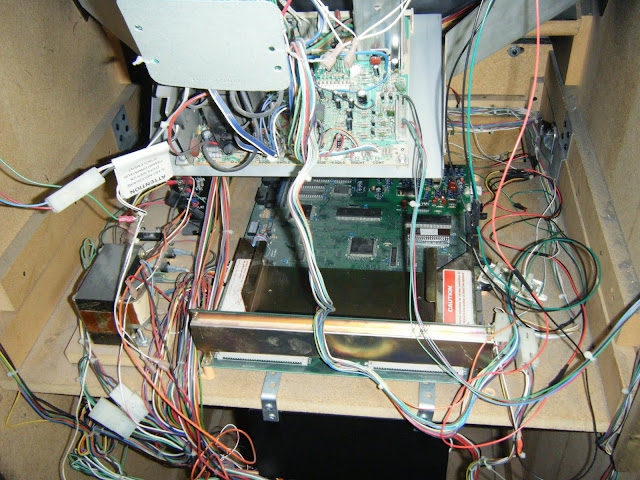
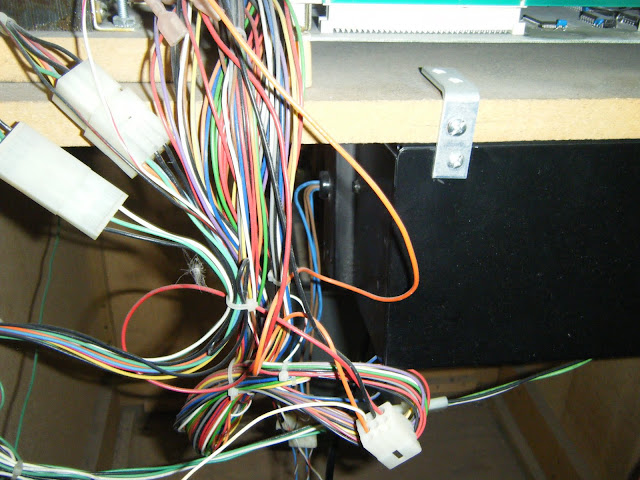
Pic #4 Black Power Supply #3 (Up Close).
Obs 1: The only wires I recognize is are the ISO-TRANS wires and the ON/OFF SWITCH wires coming form the PSU. Clearly, these look connected to something.
----
Pic #5 Bunch Of Wires (Up Close).
Obs 1: On the right hand side of the pic, there is a 9 pin molex connector with 8 wires inside. These wires lead from the molex connector to the PSU. And these wires are is NOT connected to anything. These PSU lines can run an NEO-GEO board. The pinout for these wires is the BIG STICKER on the side of the BIG BLACK PSU pictured above.
3 x RED: +5V,
3 x BLACK: GROUND,
1 x WHITE: -5,
1 x YELLOW: +12.
IMHO, you may want to check these lines out with a Multi-Meter and see if these lines read OK. You may be able to uses these power and ground lines to run your NEO.

")

")