DavidG
REAL NAME: Jason Young, KNOWN SCAMMER, , This con-
- Joined
- Nov 12, 2010
- Posts
- 372
Here are the instructions in order to install the new board. This instruction set is for all Phantom-1 boards regardless of color, revision or look.
I've added a new method to this guide which will allow you to select between a external mod or a internal one. The external mod isn't that hard while the internal mod requires a lot of work.
For those with a 3-x Neo regardless of power supply should load one of the SS games. I used SS1 as it's very clear to see if you have a ZMC2 or CMC Phantom-1. Start the game and load any stage, jump back and allow the screen to zoom out and then pause. If you see white lines then you have a ZMC2 Phantom-1 and will require the optional diode mod at the end of each guide. Note - this is for 3-x Neos and will not work on the first gen systems.
Here is a picture of SNKorSWM's Phantom-1 on a 3-4 Neo running SS1.

Again if you see white lines like in the image above you will have to perform the diode mod. If your converter is fine then you are running a first gen neo or using a CMC Phantom-1.
External Mod - Easy to Med (1h Install)
Thanks to Mr. Kev for his Phantom-1 in this mod.
Image of a Blue Phantom-1 front and back.


The back side of the converter which doesn't have the white arrow. You will need to remove the screw as seen below. Some versions use glue so take your time.

Next you will have to cut 16 lines on the board. Once cut use a meter to make sure the lines have been fully cut.

Use a marker that matches your solder mask to cover the white patches.

The upgrade board comes with two sided tape to hold the board in place. Replace the screw you removed. The upgrade board includes a plastic washer for you to use to make sure the screw doesn't short the CPLD.

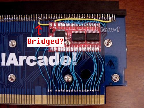
Next connect the first 16 lines you cut above to the board as shown. Once done add a line for ground and vcc. The board is labled to help you with connecting lines. Once done you will need to remove the solder mask for the same 16 lines, this time on the bottom connector. The mask comes off without much work.

Next connect the 16 bottom lines of the upgrade board to the 16 pads you just created. In this image I worked around the hole and screw as this converter will be going into a case. If your converter isn't in a case you can run wires over the holes.

Thats all you need to do to install this board. It took me an hour to install and take pictures as I went along. At this point check power and ground then test.
Optional mod for NG Dev games (Fast Striker and Last Hope) as well as a few bootleg carts.
You have many options with this one from cutting the line to this pin or lifting it. In the image I went with lifting A42 on the program board (same side you installed the upgrade board). Lift it high enough to run a wire from the board.

Next run a wire from the pad you just cleared around to the GFX board and connect it to B18.

Internal Mod - Hard to Evil (2+ hours)
SNKorSWM's Phantom-1 was used for this mod. First flip the board over and remove the six screws. Remove the GFX board.
Next on the GFX board you must remove the hardware for one of the 6 stand-offs then remove the nut. (This makes room for our board).

Next you will have to drill 36 holes in the program board, cut 16 traces and make 16 new pads. You can drill beside each trace and close to the MVS edge connector. Same as the external mod you can cut the traces and use a marker to fill in the white spots.
Note: There is no right or wrong spot to place a hole for your wires as long as you don't cut any traces while doing it. The goal of this internal mod is to upgrade the Phantom with little to no signs once done.

Closer look at the top half.

Closer look at the bottom half.

For the internal mod we can use the MVS edge connector for all the connections. Install the board into place and begin with the 20 MVS connections first then at the end connect power and ground. You can use all the labeled connections on the upgrade board to guide you.
Here is the first half of the mod done.

Here is the mod with all 36 lines connected.

Here is the finished look from the outside.

This mod in general wire for wire isn't hard but it takes a lot of time to do a clean install. I must stress to anyone going to try this to take your time.
Internal mod - NG Dev and MSX Fix.
Since we went through all that trouble to do a clean internal mod we might as well do the last two steps using the same method.
Metal Slug X requires you to run a wire from B35 on the program board to A29 on the GFX board. Run a long enough wire so you can make the connection with the boards apart.
NG Dev games such as Fast Striker require you to run a wire from A42 Program to B18 on the graphics board. You must lift or cut the connection to the MVS edge connector for A42. I prefer to lift the pin and solder to the pad under it. For the internal mod you can drill another hole for this wire on the program and graphics board then run the wire like we did before.
Here is a picture of the upgrade board installed with a wire running for the MSX, NG Dev fix and power for the diode mod.

If your Phantom-1 runs SS1 fine on your 3-x board then you're done. In this case SNKorSWM's Phantom-1 used a ZMC2 chip and does require the diode mod.
Diode mod for ZMC2 users.
This mod is only for ZMC2 users, doing this on a CMC converter will not work. This graphic issue will only be seen on 3-x revision neo's and will not be seen on first gen 5v systems.
You need to cut power on the front GFX board in two places as shown below marked with red arrows. I've made the cut, confirmed they are not connecting then used a marker to color them in. You can also see the hole used for the internal mod for NG Dev games in this image.

You will need to run a wire from VCC out on the upgrade board to this pin on the GFX board. Because the boards have to be attached its best to run the wire from the upgrade board first and leave it hanging until the end when the converter it back together. Then you can attached it to the 74LS32.

Last thing you need to do is run a wire for VCC from the bottom pad to the top pad on the inner side. You will need to remove the solder mask like you did before and run a wire around the black ring to supply the GFX board with power. Use the image below for reference.

The Diode mod is done. Images below of before and after.

That's all you need to do. All games will now be operational on all neo revisions. If it doesn't work check your connections. You also have the freedom to move the board and connect it any way you like. This guide is just one of two ways.
End result?


I've added a new method to this guide which will allow you to select between a external mod or a internal one. The external mod isn't that hard while the internal mod requires a lot of work.
For those with a 3-x Neo regardless of power supply should load one of the SS games. I used SS1 as it's very clear to see if you have a ZMC2 or CMC Phantom-1. Start the game and load any stage, jump back and allow the screen to zoom out and then pause. If you see white lines then you have a ZMC2 Phantom-1 and will require the optional diode mod at the end of each guide. Note - this is for 3-x Neos and will not work on the first gen systems.
Here is a picture of SNKorSWM's Phantom-1 on a 3-4 Neo running SS1.

Again if you see white lines like in the image above you will have to perform the diode mod. If your converter is fine then you are running a first gen neo or using a CMC Phantom-1.
External Mod - Easy to Med (1h Install)
Thanks to Mr. Kev for his Phantom-1 in this mod.
Image of a Blue Phantom-1 front and back.


The back side of the converter which doesn't have the white arrow. You will need to remove the screw as seen below. Some versions use glue so take your time.

Next you will have to cut 16 lines on the board. Once cut use a meter to make sure the lines have been fully cut.

Use a marker that matches your solder mask to cover the white patches.

The upgrade board comes with two sided tape to hold the board in place. Replace the screw you removed. The upgrade board includes a plastic washer for you to use to make sure the screw doesn't short the CPLD.

Next connect the first 16 lines you cut above to the board as shown. Once done add a line for ground and vcc. The board is labled to help you with connecting lines. Once done you will need to remove the solder mask for the same 16 lines, this time on the bottom connector. The mask comes off without much work.

Next connect the 16 bottom lines of the upgrade board to the 16 pads you just created. In this image I worked around the hole and screw as this converter will be going into a case. If your converter isn't in a case you can run wires over the holes.

Thats all you need to do to install this board. It took me an hour to install and take pictures as I went along. At this point check power and ground then test.
Optional mod for NG Dev games (Fast Striker and Last Hope) as well as a few bootleg carts.
You have many options with this one from cutting the line to this pin or lifting it. In the image I went with lifting A42 on the program board (same side you installed the upgrade board). Lift it high enough to run a wire from the board.

Next run a wire from the pad you just cleared around to the GFX board and connect it to B18.

Internal Mod - Hard to Evil (2+ hours)
SNKorSWM's Phantom-1 was used for this mod. First flip the board over and remove the six screws. Remove the GFX board.
Next on the GFX board you must remove the hardware for one of the 6 stand-offs then remove the nut. (This makes room for our board).

Next you will have to drill 36 holes in the program board, cut 16 traces and make 16 new pads. You can drill beside each trace and close to the MVS edge connector. Same as the external mod you can cut the traces and use a marker to fill in the white spots.
Note: There is no right or wrong spot to place a hole for your wires as long as you don't cut any traces while doing it. The goal of this internal mod is to upgrade the Phantom with little to no signs once done.

Closer look at the top half.

Closer look at the bottom half.

For the internal mod we can use the MVS edge connector for all the connections. Install the board into place and begin with the 20 MVS connections first then at the end connect power and ground. You can use all the labeled connections on the upgrade board to guide you.
Here is the first half of the mod done.

Here is the mod with all 36 lines connected.

Here is the finished look from the outside.

This mod in general wire for wire isn't hard but it takes a lot of time to do a clean install. I must stress to anyone going to try this to take your time.
Internal mod - NG Dev and MSX Fix.
Since we went through all that trouble to do a clean internal mod we might as well do the last two steps using the same method.
Metal Slug X requires you to run a wire from B35 on the program board to A29 on the GFX board. Run a long enough wire so you can make the connection with the boards apart.
NG Dev games such as Fast Striker require you to run a wire from A42 Program to B18 on the graphics board. You must lift or cut the connection to the MVS edge connector for A42. I prefer to lift the pin and solder to the pad under it. For the internal mod you can drill another hole for this wire on the program and graphics board then run the wire like we did before.
Here is a picture of the upgrade board installed with a wire running for the MSX, NG Dev fix and power for the diode mod.

If your Phantom-1 runs SS1 fine on your 3-x board then you're done. In this case SNKorSWM's Phantom-1 used a ZMC2 chip and does require the diode mod.
Diode mod for ZMC2 users.
This mod is only for ZMC2 users, doing this on a CMC converter will not work. This graphic issue will only be seen on 3-x revision neo's and will not be seen on first gen 5v systems.
You need to cut power on the front GFX board in two places as shown below marked with red arrows. I've made the cut, confirmed they are not connecting then used a marker to color them in. You can also see the hole used for the internal mod for NG Dev games in this image.

You will need to run a wire from VCC out on the upgrade board to this pin on the GFX board. Because the boards have to be attached its best to run the wire from the upgrade board first and leave it hanging until the end when the converter it back together. Then you can attached it to the 74LS32.

Last thing you need to do is run a wire for VCC from the bottom pad to the top pad on the inner side. You will need to remove the solder mask like you did before and run a wire around the black ring to supply the GFX board with power. Use the image below for reference.

The Diode mod is done. Images below of before and after.

That's all you need to do. All games will now be operational on all neo revisions. If it doesn't work check your connections. You also have the freedom to move the board and connect it any way you like. This guide is just one of two ways.
End result?


Last edited:
")

 )
)