prof
A Great Place to Store Your Dildo Collection
- Joined
- Jul 15, 2015
- Posts
- 1,264
Hello, I'm posting this here in case anyone else comes across the same issue with their CD unit. Hopefully, this post can help someone in the future.
A few months back I went to fire up my toploader Neo CD for the first time in a while, and after pressing power, I heard the jingle, but the screen was blank. I tried again with the proprietary a/v hookup, composite hookup and s-video hookup, and was greeted by the same bland screen each time. The discs would load, and you could hear their attract modes playing, but there was no picture. I assumed that the video encoder had gone bad, as this is a common enough issue in old consoles. The Neo CD uses the Sony CXA1645P if that is indeed the problem for someone and they need to replace it. Before jumping to any conclusions though, I took the console apart and examined everything (ribbon cable, wires, leaky capacitors, etc.) and nothing appeared out of the ordinary.
I then tested out the different transistors and little electrical components on the board to make sure everything was getting power. And sure enough, that's where I found my culprit. There are several small electrical inductors on the board, and each point registered 4.99 v on my multimeter except for one point which only read 1.5 v.
I have circled the four inductors on the video board. Note that the ring colors are yellow, purple, black, silver.
Here is a link to compatible replacements on amazon: https://www.amazon.com/dp/B07XYW4L16?psc=1&ref=ppx_yo2ov_dt_b_product_details
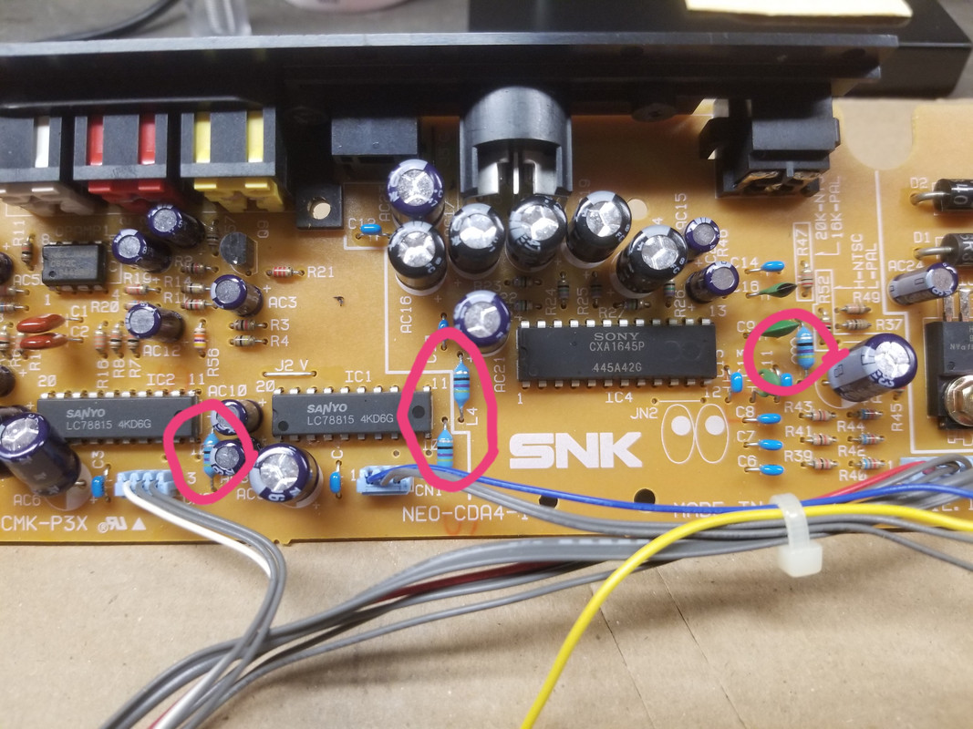
The bottom point on the far right inductor is the one that read 1.5 v, but I would assume that this same problem could happen if any of the inductors went bad.
Once I figured out what the problem was, and had the new inductors in hand, I stuck each end of the inductor wire into the little point hole just to test it out before soldering it in. Like so:
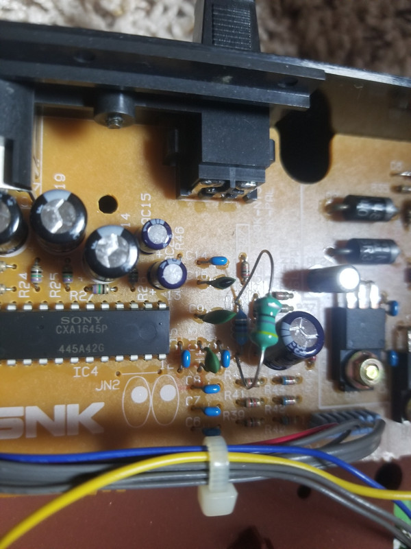
And sure enough, that gave me picture. So I knew that was my issue, and this replacement would fix it.
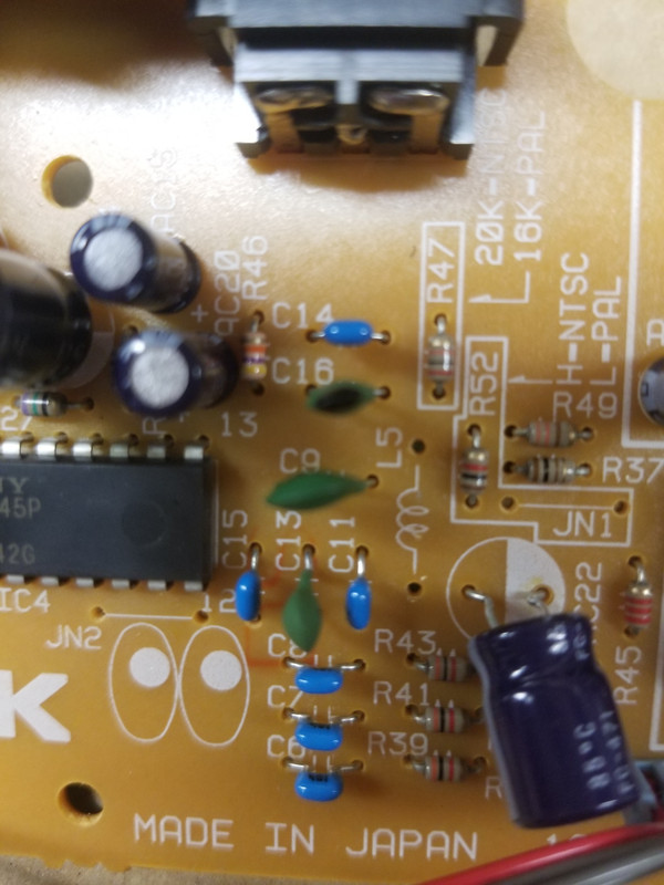
So I removed the old solder and took out the bad inductor, and replaced it with the new one. Soldering it into the board.
The board where the bad inductor was removed, it's at the L5 mark:
And the new inductor soldered into place:
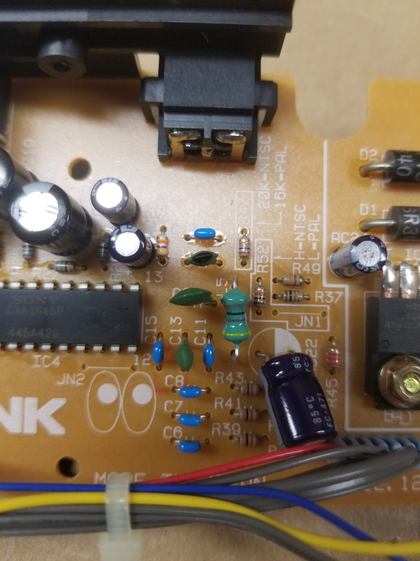
Make sure to line up the inductor the correct way. In this case, the yellow stripe was at the bottom. It's a good idea to take photos of the board prior to removing any components, so that you don't mistakenly install the replacement backwards.
The moment of truth.....


If anyone else comes across this problem and has any questions, feel free to shoot me a message.
-Adam
A few months back I went to fire up my toploader Neo CD for the first time in a while, and after pressing power, I heard the jingle, but the screen was blank. I tried again with the proprietary a/v hookup, composite hookup and s-video hookup, and was greeted by the same bland screen each time. The discs would load, and you could hear their attract modes playing, but there was no picture. I assumed that the video encoder had gone bad, as this is a common enough issue in old consoles. The Neo CD uses the Sony CXA1645P if that is indeed the problem for someone and they need to replace it. Before jumping to any conclusions though, I took the console apart and examined everything (ribbon cable, wires, leaky capacitors, etc.) and nothing appeared out of the ordinary.
I then tested out the different transistors and little electrical components on the board to make sure everything was getting power. And sure enough, that's where I found my culprit. There are several small electrical inductors on the board, and each point registered 4.99 v on my multimeter except for one point which only read 1.5 v.
I have circled the four inductors on the video board. Note that the ring colors are yellow, purple, black, silver.
Here is a link to compatible replacements on amazon: https://www.amazon.com/dp/B07XYW4L16?psc=1&ref=ppx_yo2ov_dt_b_product_details
The bottom point on the far right inductor is the one that read 1.5 v, but I would assume that this same problem could happen if any of the inductors went bad.
Once I figured out what the problem was, and had the new inductors in hand, I stuck each end of the inductor wire into the little point hole just to test it out before soldering it in. Like so:
And sure enough, that gave me picture. So I knew that was my issue, and this replacement would fix it.
So I removed the old solder and took out the bad inductor, and replaced it with the new one. Soldering it into the board.
The board where the bad inductor was removed, it's at the L5 mark:
And the new inductor soldered into place:
Make sure to line up the inductor the correct way. In this case, the yellow stripe was at the bottom. It's a good idea to take photos of the board prior to removing any components, so that you don't mistakenly install the replacement backwards.
The moment of truth.....
If anyone else comes across this problem and has any questions, feel free to shoot me a message.
-Adam