MV4-FT2 - watchdog even with neogeo diagnostic bios

ack

Ninja Combat Warrior
15 Year Member
Joined
Apr 9, 2009
Posts
540
Now for the jailbars on slot 4 - this might be a bit harder as there is not such an obvious starting point. Luckily slot 3 works perfectly, so I can use that for clues.

I usually do something like this.

Put a game in slot 3, and go to unibios's hardware test screen to get to the cross hatch. Press D to go into the memory view and scroll down to address 0x000100. On the right hand side you should see NEO-GEO. Take a picture of this screen.

Put the same game into slot 4, let it boot to the cross hatch screen. Press D to go into the memory view and scroll down to address 0x000100 again, take a picture. The compare the pictures to try and deduce what the issue is.
 

maki

Edo Express Delivery Guy
Joined
Jan 1, 2022
Posts
334
Now for the jailbars on slot 4 - this might be a bit harder as there is not such an obvious starting point. Luckily slot 3 works perfectly, so I can use that for clues.
can you share a pic of those "jailbars" (or link if you shared i already?)

if the DIAG BIOS says everything is fine, it is often something that can't be tested by such SW, like connection to the cart slot (missing signals) or communication between the main ICs (ie. LSPC2-A2 to B1) because of disrupted traces

I have to say I'm in awe for your persistence on these MVS, multi slot boards can be quite complex to fix
 

hatmoose

Kuroko's Training Dummy
Joined
Dec 3, 2021
Posts
79
I have to say I'm in awe for your persistence on these MVS, multi slot boards can be quite complex to fix

I was thinking about this the other day - I've probably learned more about electronics and repair working on this in the last 2 weeks than I have in my life up until now. Huge thanls to Maki, Ack, Sluggerdan and the other responders - I hope to be able to return your kindness and expertise one day.

Update for today is that I have traced and checked continuity for every single pin (all 240 of them!) on slot 4 back to the G0/244/253/153/Etc.
Good news, they all work and I have written down the pinout - I will share on the wiki in the next few days!
Bad news, they all work. So every single trace from the cart to the IC is fine.

That being the case; either one of the custom IC's itself is faulty, or one of the traces from one of the custom IC's to the board-board connectors is bad.

There is a partial pinout of the top board for 2 of the customs in this thread
http://newlifegames.com/nlg/index.php?topic=1859.0
Unfortunately there are 15 customs and each of them is 64 pins. thats a lot of checking...

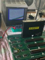
@maki to answer your question - these are the jailbars of which I speak

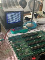
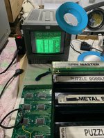
No carts inserted = jailbars (crosshatch?)
IMG_0260.jpeg

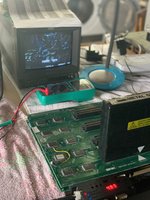
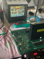
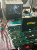
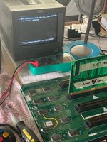
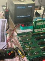
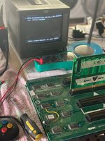
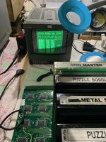
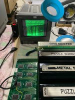
Cart in slot 1/2/3 = all good
IMG_0261.jpegIMG_0262.jpegIMG_0263.jpeg

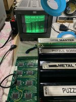
Cart in slot 4 = jailbars/crosshatch
IMG_0264.jpeg

Neo geo Diagnostics + Z80 reporting no error in slot 1,2,3,4 the z80 test jingle plays as expected
IMG_0265.jpegIMG_0267.jpeg

@ack Will try and do that now - I have this annoying bug with the unibios on this board where it will boot to a black screen if slot 1 is not populated. Not sure if having a cart in slot 1 is going to mess up the test results - but I suspect it will...
 

Attachments

  • IMG_0266.jpeg
    IMG_0266.jpeg
    2.4 MB · Views: 2

hatmoose

Kuroko's Training Dummy
Joined
Dec 3, 2021
Posts
79
@ack Have tried but without success.

Unibios exhibits weird behavior when there is nothing in slot 1 (I believe this is a known bug with the unibios in some 4-slot boards)

If slot 1 is populated everything works as expected (except slot 4 is dead of course)
If none of the slots are populated it does not boot to crosshatch, it boots to a white flash that repeats every 5 seconds
if slots 2 and/or 3 are populated but slot 1 is empty it works expected but with no sound
if slots 1 and 2 and 3 are all empty it boots to a white flash, regardless of what is in slot 4
 

ack

Ninja Combat Warrior
15 Year Member
Joined
Apr 9, 2009
Posts
540
The goal is just to take a picture of that memory location using the same game in a working slot and slot 4, so you can compare them. You can have all slots populated if need be.
 

hatmoose

Kuroko's Training Dummy
Joined
Dec 3, 2021
Posts
79
This was a combination of me being a massive noob, not knowing my tools, and not having the right tool for the job.

Eventually I accomplished this simple task as follows.

If anyone else reads this in future; Be aware that the Minigun Supergun maps the "select" button to "coin" on the jamma edge. Normally this is useful and practical behavior. Except in the very rare case of multislot MVS's when you need the select button to send select (jamma pin D/26) to change the memory viewer slot.
So if you have a 4 button controller plugged into your Minigun Supergun (like the neogeoCD control pad for example) you cant actually press select...

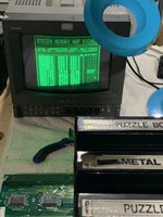
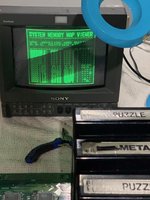
Having learned that useful piece of info I was able to get these photos.

Slot 1
IMG_0326.jpeg

Slot 2
IMG_0325.jpeg

Slot 3
IMG_0324.jpeg

Slot 4 - slot 4 is properly messed up - some of the addresses actually flick between values.
IMG_0323.jpeg

Here are some more slot 4 pictures just in case
IMG_0319.jpegIMG_0322.jpeg
 

ack

Ninja Combat Warrior
15 Year Member
Joined
Apr 9, 2009
Posts
540
Took me a sec to realize your picture labels were all wrong, heh.

If you compare these 2 pictures, it points to what the issue is

https://www.neo-geo.com/forums/index.php?attachments/img_0325-jpeg.56579/ (puzzle bobble in slot3)
https://www.neo-geo.com/forums/index.php?attachments/img_0319-jpeg.56582/ (puzzle bobble in slot4)

At address 0x000102 you have data of 0x4F2D on the good slot and 0x4F25 on the bad slot. The different between them is data bit 3 is stuck low on the bad one. If you check other data values on the good slot that have bit3 high and compare those to the bad slot they are low.

ie:
0x000114 0x0099 -> 0x0091
0x00011C 0x034C -> 0x0344
0x000120 0x0498 -> 0x0490

So you will want to examine/trace D3 (pin A8 on the prog board/slot) to where ever it goes.
 

hatmoose

Kuroko's Training Dummy
Joined
Dec 3, 2021
Posts
79
Got it - now that I know what I'm looking for I realise that I made it much harder than I needed to with those photos, sorry about that, and thank you for your patience

Working backwards
I traced address line D3 which is pin A8 on the prog board for each slot
Slot 4 PROG A8 to NeoG0@D1 pin1 = continuity
Slot 3 PROG A8 to NeoG0@D1 pin9 = continuity
Slot 2 PROG A8 to NeoG0@B1 pin21 = continuity
Slot 1 PROG A8 to NeoG0@B1 pin1 = continuity

So all the D3 lines are making it from their NEO-G0 to the slot OK

For slot 3 and 4 it looks like the NEOG0 @D1 splits out the signal it gets on pin 5 and sends it to pin 1 (for slot4) and pin 9 (slot 3)

NeoG0@D1 pin 5 goes to CN10 pin A7 on the top board = continuity
So the D3 line is making is making it from the top board connector to the NEO-GO@D1 OK

CN10A7 on the top board goes to CN10A7 on the bottom board = continuity
So the D3 line is making it from the bottom board to the top board OK

CN10A7 on the bottom board goes to pin 5 of the AS245 at C11 on the bottom board
So the D3 line is making it from the AS245 at C11 to the bottom board connector OK

All of the input pins on the AS245@C11 (13-20) are wired directly to the bios pins 12-19 = continuity
So the D3 line is making it from the BIOS to the AS245@C11 OK

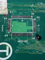
All the traces are good - really that leaves me with a possible bad AS245@C11 or a possible bad NEO-G0@D1

Changed the AS245 = no improvement (I didnt really expect that there would be, but it was much easier than changing the NEO-G0

Looking inside the NEO-G0@D1 it looks like it is made of 4 x AS245’s all mashed to together on one chip
https://wiki.neogeodev.org/index.php?title=File:Neo-g0_internal.png

All of the problems seem to be associated with the address lines for slot 4, all of which are switched in what used to be U3, an AS245, before they all got bundled together onto the custom.

So next up I shall change the NEO-G0 @D1
 

hatmoose

Kuroko's Training Dummy
Joined
Dec 3, 2021
Posts
79
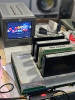
Flawless victory! Now works perfectly in every slot

I raided the MV4F for parts and swapped the NEO-G0 onto the MV4-FT2, that resolved the crosshatch on slot 4 and returned the board to "fully working"

Huge thanks to @ack @maki @slugger_dan and many others. You have taught me new things and made me a more useful member of the community. One day I hope to pay it forward and return your kindness by helping others too.

In the process of doing this I've learned some new things that are not already in the wiki (pinouts and etc) so I'll add those over the next few days too.

IMG_0334.jpegIMG_0338.jpeg

This was the most fun I've had in a long time! Now looking for a 6-slot in New Zealand/Aussie that I can work on to really test my new skills :-)
 
Top