GadgetUK
Gai's Trainer

- Joined
- Sep 27, 2013
- Posts
- 1,328
I cannot remember off the top of my head how the banking works, but typically it's going to involve use of one or more of the upper address bits. Since you are getting bad CRCs on both games there, and the banking error too, I would guess that at least one of the upper address lines is not making connection to wherever its supposed to go to the main chipset on the motherboard (with regards to the P bus). Since you are using a 4 slot, there's a lot of buffering logic etc that sits inbetween each slot and the chipset. Since all slots are behaving the same, I would assume from that the clue that a) slot specific buffering of inputs is not the problem b) connectivity between the chipset and the buffering of upper address line(s) could be a problem though. Anyone have any 4 slot schematics? You really need to take a look at the schematics (if there are any) and trace the upper address bits from chipset through buffers etc, and check those chips with a logic probe. My guess is perhaps a faulty 74LS244 or 74LS245, or perhaps a fault on one of the 74LS74 chips. You could buy a spare of each of those types of chips, and try the piggy back method (bend the pins of the new chip inwards slightly, and 'slide' the chip over the top of the chip you want to test - but it has to make a nice snug fit, gripping each pin properly). That technique can often help identify a faulty 74 chip if you've not got a logic probe or logic analyser. Depending on the board, I think some boards use the 'neo buff' chip, which basically is 2 x 74HC245 in one packaged - if you have those you really need to test with logic analyzer, scope or logic probe.
The main thing I would suggest is going over the board with a magnifier really closely and inspect for damage. Broken traces are often the most likely cause.
Also, measure the 5v on the cart slots too. You get voltage drop on these multislot boards and if the PSU is not beefy enough you could measure 5.1v at JAMMA and then 4.8 on a slot... You should measure at least 5.0v on the slot edges imo to ensure its OK.
EDIT: Looking at the schematics that are available (1 slot) - The Neo C1 seems to relate to some of the banking (PORTxxxx) connectivity. Depending on the board you may or may not have a C1 - the logic might be merged with something else. If you do have a C1 I would certainly check around that chip and try and follow its connectivity to (and through) the buffering logic perhaps.
EDIT2: Having said all of that, I just re-read and you are suggesting that several other games work OK? Have you CRC checked those other games to make sure they are coming back OK? If its just these two games and other games work 100%, I would assume its the games themselves or voltage drop related perhaps.
Last edited:
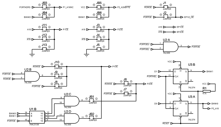
") Funnily enough that's the same diagram I was looking at before my last post lol. Great idea applying VCC / gnd to the pad and test to see if the signal passes through to the cart.
Funnily enough that's the same diagram I was looking at before my last post lol. Great idea applying VCC / gnd to the pad and test to see if the signal passes through to the cart.