CMVS 4 Slot (PSU question) N00b to Forums/ modding

Tengugurl

Cheng's Errand Boy
Joined
Feb 9, 2017
Posts
111
Hello,

I have a Neo Geo MVS 4-25 PCB that I am making into a CMVS 4 slot (ish....) (I know right?! why not get a MV1FZ because there is no documentation on CMVS 4slots lol)

The PCB is in working order (Cap kit done last year) and CGA/VGA pcb added to work outside of my cab.

I want to make a Supergun (out of an aluminum project box) to power the MVS (Leave it stock as much as possible) so I am using a new PSU and Rocker Switch to power the 2.1mm jack.

Here is the guide I am following to make a CMVS (it is for a 2 slot but should work...)
http://www.jamma-nation-x.com/jammax/cmvs2slot.html

List of items to Power the new Jamma harnass/ MVS:

1) PSU (+5v 6Amp as it is a 4 slot)
https://www.amazon.com/gp/product/B01EAF4YNE/ref=oh_aui_detailpage_o00_s00?ie=UTF8&psc=1

2) Rocker Switch able to handle the Amps from the PSU:
https://www.amazon.com/gp/product/B00WKNXWRS/ref=oh_aui_detailpage_o00_s00?ie=UTF8&psc=1

3) Female PSU jack:
http://www.ebay.com/itm/281278886620


I have a silly question...

I do not want to solder to the board and make a female PSU jack on the Heat shield, rather, I'd like to have it on the Supergun (Project box) but, I am not sure if I can use the Jamma harness +5v and -ground to power the console..... Is it possible?

So in sum,
I am looking to see if I can send 5+v 6Amp signal through the Jamma cable to the MVS Jamma edge without breaking my console.

Thanks for your help loves <3
Tengugurl


Link to the Jamma pinout in question
http://farm6.static.flickr.com/5149/5569027243_9570423c3a.jpg
 
Last edited:

GadgetUK

Ace Ghost Pilot
Joined
Sep 27, 2013
Posts
1,323
See my recent 4 slot video here (near the end I show where I soldered the +5 and ground wires, and also removed the 7805 and joined up the 5v input to the 5v power in.

https://www.youtube.com/watch?v=LWQaMOMbp5s See around 16:03 there. That's the underside of the bottom board shown at 16:03.

Just make sure you get your +5v and ground the right way around. Personally I would also add a fuse, and a beefy diode reverse biased (just to protect against reverse polarity). I will be doing both of those things to my 4 slot later.

I know you said you don't want to solder, but it really isn't hard soldering a couple of power wires under the JAMMA edge there. Just a $15 soldering iron, some 60/40 solder with flux and you're done.
 
Last edited:

Tengugurl

Cheng's Errand Boy
Joined
Feb 9, 2017
Posts
111
Hey there!

I had a look at your video and subscribed :) (P.s thanks!)

Thanks for the quick reply, I like your craftsmanship and it definitely sounds like you have the right idea when it comes to safety.

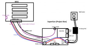
I drew up a schematic here to show you what I am thinking...
I am not against soldering (quite enjoy nerding out on soldering) but the thing is, I want the SuperGun (Project box) to house all the components so I can use it on another Arcade PCB if I wanted.

Please see the image below and let me know if you think it would be possible to run power from the Wall socket into the Jack into the JAMMA cable into the board via the JAMMA edge. (Completely bypassing the need to do anything to the board)


supergun schecmatic.png

I look forward to your reply :)
Tengugurl
 

Xian Xi

JammaNationX,
15 Year Member
Joined
Dec 1, 2005
Posts
27,750
If you are making a supergun just put an arcade power supply in there instead of the 5v one.
 

GadgetUK

Ace Ghost Pilot
Joined
Sep 27, 2013
Posts
1,323
Yes, you can use your supergun there, but the audio outputted on the JAMMA edge is amplified - if you do this, you will need to make sure the volume level is set very very low (start with sound off), then increase the volume a tiny bit until you can hear it. If you go too loud you could damage whatever you have connected to the 3.5mm socket (eg. your TV, or amp, headphones etc). If you see the earlier part of the video you can see the mod I did to feed the headphone audio out through one of the 3.5mm sockets. You could also just get a connector to plug directly onto the headphone output (the white plastic connector - 4 pin, no idea what that type of connector is called but someone should know) - that is a safer way to take audio out of the 4 slot and into the SuperGun / TV etc. What I don't understand is why you are showing wires from the MVS to the supergun there - the supergun should have a JAMMA connector on it, if you just plug it into the MVS you're done. All you need to do is deal with the power and audio.

EDIT: Also, I see you have lines there indicating you might wire up the DB15's - why do that, the 4 slot has the 2 DB15 controller ports on it!?!?

Hey there!

I had a look at your video and subscribed :) (P.s thanks!)

Thanks for the quick reply, I like your craftsmanship and it definitely sounds like you have the right idea when it comes to safety.

I drew up a schematic here to show you what I am thinking...
I am not against soldering (quite enjoy nerding out on soldering) but the thing is, I want the SuperGun (Project box) to house all the components so I can use it on another Arcade PCB if I wanted.

Please see the image below and let me know if you think it would be possible to run power from the Wall socket into the Jack into the JAMMA cable into the board via the JAMMA edge. (Completely bypassing the need to do anything to the board)


View attachment 42542

I look forward to your reply :)
Tengugurl
 
Last edited:

Tengugurl

Cheng's Errand Boy
Joined
Feb 9, 2017
Posts
111
Thank you so much everyone!

That confirms my assumption with regards to the 5v PSU to the JAMMA unit. I will be careful as you had stated GadgetUK, I made sure to go out and get an inline Fuse to ensure nothing happens.

Lol you may think I am crazy to add Db15s to the case but it is so I can use the project box as a Supergun. (So I am really not making a CMVS just the lessons learned from a CMVS and incorporating it into a Supergun)

@Xian Xi - Smart thinking! I have updated my schematics so I can have the 2.1mm 5v 6amp PSU as well as the stock unit (in case it needs the 12v etc..)

I can't wait to post some final products on this but for now I am waiting for the mail to ship everything lol

Thanks again!
 

GadgetUK

Ace Ghost Pilot
Joined
Sep 27, 2013
Posts
1,323
It will need 12v for sound, unless you remove the 7805 from the MVS and join its output (pin 3) to the 5v JAMMA in.
 

Xian Xi

JammaNationX,
15 Year Member
Joined
Dec 1, 2005
Posts
27,750
It will need 12v for sound, unless you remove the 7805 from the MVS and join its output (pin 3) to the 5v JAMMA in.

Ah, you don't even need to remove the 7805, just join the two 5v rails.
 

GadgetUK

Ace Ghost Pilot
Joined
Sep 27, 2013
Posts
1,323
Ah, you don't even need to remove the 7805, just join the two 5v rails.
Yeah, I realise that, but why not reclaim an unused 7805 whilst you are there! You can never have enough 7805's =D

I did the same thing with the Hitachi audio amp on my 1FZ. After doing the 5v mod and stereo audio out via MKL's audio amp there was no point leaving the amp on there.
 
Last edited:

Tengugurl

Cheng's Errand Boy
Joined
Feb 9, 2017
Posts
111
I am going to sound really dumb but where is the 7805? I want to join it to the Jamma edge as you all had stated but I am still learning :(
 

Xian Xi

JammaNationX,
15 Year Member
Joined
Dec 1, 2005
Posts
27,750
Yeah, I realise that, but why not reclaim an unused 7805 whilst you are there! You can never have enough 7805's =D

I did the same thing with the Hitachi audio amp on my 1FZ. After doing the 5v mod and stereo audio out via MKL's audio amp there was no point leaving the amp on there.

Leaving it in is more for if he ever wants to use it in a cab again. If he never plans to, then by all means remove it and use it somewhere else.
 

Xian Xi

JammaNationX,
15 Year Member
Joined
Dec 1, 2005
Posts
27,750
Doesn't the 7805 do something if fed +5V on its output? just curious, I have no idea if it does or not.

Not that I've experienced. On multi slot consolizations I leave them in.
 

aha2940

AH, A, COLUMBIAN!,
Joined
Dec 15, 2013
Posts
2,528
Leaving it in is more for if he ever wants to use it in a cab again. If he never plans to, then by all means remove it and use it somewhere else.

I'm confused James: if you join the +5V rail with the +5V rail feeding the amplifier (the ouput of the 7805), why would you need the 7805? wouldn't all the board get fed with only +5V from the JAMMA edge and work properly? I think I am missing something here...
 

Xian Xi

JammaNationX,
15 Year Member
Joined
Dec 1, 2005
Posts
27,750
I'm confused James: if you join the +5V rail with the +5V rail feeding the amplifier (the ouput of the 7805), why would you need the 7805? wouldn't all the board get fed with only +5V from the JAMMA edge and work properly? I think I am missing something here...

Yes, that's correct. Man, this new baby is draining my sleep and it's starting to show...lol I think I was mixing up what MKL told me with something else. Now when I remember it, he was talking about my tutorial saying to remove it and he just replied that you just didn't need to remove it and then I paired it with the FZ reply where you cut the +12v trace to the amplifier. That's what happens when you sleep at 3am and wake up and 630am for a week...lol
 

GadgetUK

Ace Ghost Pilot
Joined
Sep 27, 2013
Posts
1,323
I believe there are two 5v supplies (5v from JAMMA edge, and 12v fed through the 7805) - perhaps to do with limiting noise on the audio section. TBH I am not sure whether the headphone output will still work without joining up the output pin of the 7805 to the main 5v supply - I suspect its feeding some of the opamps. Otherwise there's no reason for a 7805 at all, and I am 100% sure that 7805 isn't feeding the main logic, it cannot provide anywhere near enough current.
 
Last edited:

Xian Xi

JammaNationX,
15 Year Member
Joined
Dec 1, 2005
Posts
27,750
The opamps require 5v for sound production that comes from the 7805 so you need the bridge for the headphones to have sound.
 
Top