AD725 Dot Crawl

mikey

Marked Wolf
Joined
Jun 19, 2012
Posts
215
I have built a supergun and consolized an mvs using the AD725 and a layout I did myself on perfboard. Both suffer from the exact same type of dot crawl. I'm not sure if this is typical of the chip specifically or if it is due to an error in my layout or something else. Weird thing is, when I used a specific type of power jack, I moved the plug around and the dots would crawl from the left to right, then to the right from the left, or would speed up and slow down, or even stop. At the bottom is a link to a video of the dot crawl. If you look close you can see the changes as I wiggle and rotate the power cord in the actual jack on the supergun. I changed the jack and it seems to have become more consistent, but the dot crawl is still there. Here the video link:

http://videobam.com/IkTPQ

And here is my layout:
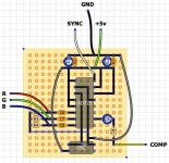
rgb encoder.png

I should also mention that since I initially built this I added the luma trap, a 0.1uf cap from +5v to ground on the oscillator, and a sync cleaning circuit using an LM1881 where I also connected the vertical sync to the 725.

Any ideas?

Thanks!
 

HeavyMachineGoob

My poontang misses Lenn Yang's wang
10 Year Member
Joined
Apr 3, 2011
Posts
5,857
Perhaps you're not using enough ground, or insulation from main power sources.
 

shadowkn55

Genbu's Turtle Keeper
15 Year Member
Joined
Dec 9, 2006
Posts
2,386
Try adding the luma trap to the circuit. That would be a 68uh inductor and 27pf cap on pin 12.
 

mikey

Marked Wolf
Joined
Jun 19, 2012
Posts
215
Thanks for the replies. I did add the luma trap, however I used a 9pf cap, would that make a noticeable difference compared to 27pf?

I'm not sure how I would go about adding more ground or insulating the circuit more. Would the position of the oscillator make a difference here? The clock signal is going up right through all the pin connections of the 725. Would it be better to move the oscillator up to the left so that it is right beside the clock input for the chip? I remember reading somewhere that you should keep clock signals as short and close to the destination as possible.
 

malignantpoodle

Robert Garcia's Butler
Joined
Aug 21, 2010
Posts
1,281
I'm no expert in these matters but I do occasionally notice this kind of thing using factory made encoders, but not near as profound as how it looks in your video.

Just throwing out there that it could be a ground or more likely a sync issue. You've tried a different screen? I'd be tempted to try a different power source as well.
 

HeavyMachineGoob

My poontang misses Lenn Yang's wang
10 Year Member
Joined
Apr 3, 2011
Posts
5,857
Thanks for the replies. I did add the luma trap, however I used a 9pf cap, would that make a noticeable difference compared to 27pf?

I'm not sure how I would go about adding more ground or insulating the circuit more. Would the position of the oscillator make a difference here? The clock signal is going up right through all the pin connections of the 725. Would it be better to move the oscillator up to the left so that it is right beside the clock input for the chip? I remember reading somewhere that you should keep clock signals as short and close to the destination as possible.

Adding more ground would include soldering an extra wire or two. Insulation can be achieved by moving the two conflicting parts away from each other, but usually you have to add something like an RF shield. In this case however, that'd be rather hard.

Definitely a good idea to put that oscillator closer to the clock input of the chip, even if it means extending the voltage and ground wires a bit.
 

malignantpoodle

Robert Garcia's Butler
Joined
Aug 21, 2010
Posts
1,281
You're using composite only right? Not svideo?

IMO it can't be helped. Composite has nasty crawl every time I've used it. Wire in s-video instead.
Pin 9 Chroma, Pin 11 Luma.

You're hooked in 10 which is comp.
 

Xian Xi

JammaNationX,
15 Year Member
Joined
Dec 1, 2005
Posts
27,750
Could also be from the power supply if it's a cheap one. Luma trap should show a good difference though.
 

mikey

Marked Wolf
Joined
Jun 19, 2012
Posts
215
Well, i moved the oscillator up the board closer to the 725 pin, made the cap in the luma trap 27pf, tried adding another ground connection, cleaned in between all the solder points, and still no difference. I have also tried two different power supplies, and it's the same problem with both (both power supplies are 5v dc wall warts, one is 2 amps, the other is a 4 amps). I have no idea what could be causing this. Should I be regulating the power? I have a 7805, but I think it's only good for 1 amp. I also think this is some sort of power or grounding problem, i just can't pinpoint the issue.

I would definitely prefer to use s video, but neither of my tv's support it... so I'm screwed there.
 

mikey

Marked Wolf
Joined
Jun 19, 2012
Posts
215
I don't seem to have this issue with any other systems using composite on either of my tv's, my genesis, snes, and nes all work well (and by that I mean the composite looks crappy as ever, but there's no crawling/ripple effect).

What are other people's experiences with this chip? Is this a common issue, or do you get a "relatively clean" composite picture?
 

shadowkn55

Genbu's Turtle Keeper
15 Year Member
Joined
Dec 9, 2006
Posts
2,386
I don't seem to have this issue with any other systems using composite on either of my tv's, my genesis, snes, and nes all work well (and by that I mean the composite looks crappy as ever, but there's no crawling/ripple effect).

What are other people's experiences with this chip? Is this a common issue, or do you get a "relatively clean" composite picture?

That's exactly the point that viletim is trying to make in that post. All three of those systems you mentioned run on a multiple of the colorburst frequency f=3.579545mhz. (NES = f/2, Genesis = 2f, SNES = f). The colorburst signal is generated internally in the system so the composite color encoding is more accurate so to speak.

If you look across the older generation of consoles, running on a multiple of colorburst was a common occurrence. The notable exception is the Neo Geo, it runs at a master clock of 24mhz and is not divisible by 3.579545mhz at all.

http://en.wikipedia.org/wiki/Colorburst
 

mikey

Marked Wolf
Joined
Jun 19, 2012
Posts
215
That makes sense about the clock frequency. Did the AES suffer from something similar to this then? I know it used the CXA1145 to encode the video.

Thanks for all the feedback help by the way
 

HeavyMachineGoob

My poontang misses Lenn Yang's wang
10 Year Member
Joined
Apr 3, 2011
Posts
5,857
If you find out the AD725 isn't cutting it for your needs, I'd like to recommend the Sony CXA2075. It's application circuit is very simple and it's video output is amazing. Only problem is it's only available as a tiny surface mount chip.
 

mikey

Marked Wolf
Joined
Jun 19, 2012
Posts
215
Sorry to bring back this thread, but I just wanted to post that the issues were with the power supplies I used. I tried a few different wall warts and then changed over to a power supply from an old hard drive enclosure, and the problem went away. The picture looks great now (for composite, that is).

Thanks for all the help and feedback, just wanted to post the fix.
 
Top