You are using an out of date browser. It may not display this or other websites correctly.
You should upgrade or use an alternative browser.
You should upgrade or use an alternative browser.
RGB bypass mod
- Thread starter Adamaki
- Start date
- Joined
- Mar 8, 2002
- Posts
- 3,686
And yet, according to this page the checkerboard effect shows up even with an official RGB cable.
http://nfggames.com/games/neorgb/
http://nfggames.com/games/neorgb/
- Joined
- Dec 1, 2005
- Posts
- 27,750
And yet, according to this page the checkerboard effect shows up even with an official RGB cable.
http://nfggames.com/games/neorgb/
I wonder if it's from the ground on the AV socket, kinda weird. I took ground from the IC to the right of the CXA and it went away.
Some revisions I notice have bypass caps at the power socket, maybe it's needed for the 3-5?
Old thread but pretty much what I'm after, Xian, you're probably my man again on this.
I've picked up a 3-4 AES and have the 'checkerboard' issue, this is low serial and does not have the lines but want to clean up the image, do I need to do a bypass or is there a way of improving the ground to get rid of it ?
Cheers
Dave
I've picked up a 3-4 AES and have the 'checkerboard' issue, this is low serial and does not have the lines but want to clean up the image, do I need to do a bypass or is there a way of improving the ground to get rid of it ?
Cheers
Dave
- Joined
- Dec 1, 2005
- Posts
- 27,750
Old thread but pretty much what I'm after, Xian, you're probably my man again on this.
I've picked up a 3-4 AES and have the 'checkerboard' issue, this is low serial and does not have the lines but want to clean up the image, do I need to do a bypass or is there a way of improving the ground to get rid of it ?
Cheers
Dave
Just do the bypass, the 3-4 needs it as the picture is very dim even when you update the caps and resistors to the proper ones.
Thanks Xian
Couldn't find a guide for the 3-4 when asked the question but have now, the RGB is a million times better out the box than the 3-6 and wouldn't have known the difference if did not have the CMVS or do the mod on the 3-6. I've changed to this AES as is like new, the box is unmarked also and got for a great price :-)
Cheers
Dave
- Joined
- Dec 1, 2005
- Posts
- 27,750
Hi Xian, i have a revision 3-5, i plan to fix the audio issue with a cap but is it worth doing the rgb bypass?
Thanks.
On a 3-5 the RGB is already nice and bright, the only time you need to do a bypass is if you are seeing a checkerboard pattern.
On a 3-5 the RGB is already nice and bright, the only time you need to do a bypass is if you are seeing a checkerboard pattern.
Thanks for that, unfortunately i'm having to return the system as most of my games won't work, some reset and others show graphical problems.
Color cycling effect after mod
I have a 3-6 version NTSC board with serial 236k-something. Today I managed to get a friend over with proper electronics and soldering skills to help out with the RGB-bypass mod. He followed the guide at www.jamma-nation-x.com titled May 21 2009 : RGB Bypass Mod for Your AES Board Revision 5 to 7. The board now looks like this:

Unfortunately, the displayed picture is not stable, for lack of a better word. It linearly goes from the desired result to a reddish or greenish taint, then back to normal and this cycle keeps on going for a few minutes until the picture settles for a very reddish taint. The cable used is an original unmodified Neo-Geo RGB SCART cable. Does anyone see anything wrong with the work done?
On another note, the main thing we were trying to fix was that the controller ports are not working properly. When playing, randomly different buttons or directions on the stick stop working, which can be mitigated by moving/repositioning the end of the controller cable. We thought it was a classic dry joints problem, but resoldering didn't work. The controllers work flawlessly when connected to my supergun, so the problem must be with the console. Cleansing with electrical cleaner doesn't work either. Any ideas on what might be wrong?
Any input on either of the problems is very much appreciated! I'm so much longing for finally having a perfectly working AES-system, without any annoying issues!
I have a 3-6 version NTSC board with serial 236k-something. Today I managed to get a friend over with proper electronics and soldering skills to help out with the RGB-bypass mod. He followed the guide at www.jamma-nation-x.com titled May 21 2009 : RGB Bypass Mod for Your AES Board Revision 5 to 7. The board now looks like this:
Unfortunately, the displayed picture is not stable, for lack of a better word. It linearly goes from the desired result to a reddish or greenish taint, then back to normal and this cycle keeps on going for a few minutes until the picture settles for a very reddish taint. The cable used is an original unmodified Neo-Geo RGB SCART cable. Does anyone see anything wrong with the work done?
On another note, the main thing we were trying to fix was that the controller ports are not working properly. When playing, randomly different buttons or directions on the stick stop working, which can be mitigated by moving/repositioning the end of the controller cable. We thought it was a classic dry joints problem, but resoldering didn't work. The controllers work flawlessly when connected to my supergun, so the problem must be with the console. Cleansing with electrical cleaner doesn't work either. Any ideas on what might be wrong?
Any input on either of the problems is very much appreciated! I'm so much longing for finally having a perfectly working AES-system, without any annoying issues!
I was looking around for info about the RGB bypass for my AES3-5 model and I found the following schematic from MKL.
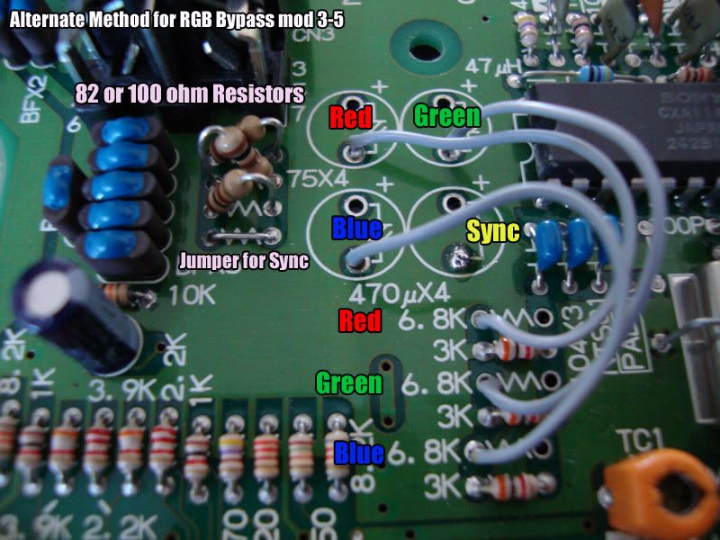
So I have a question for MKL.... whats the point of jumpering the 75Ohm resistor's spot (jumper for Sync) since the track leads to the negative pole of the composite capacitor that has already been removed?
Also another thing.... Should I use 82 or 100ohm resistors? Why two values to choose from? Whick one is better?
Is this mod exactly the same as the other one with the connections on the back of the board or is it inferior in some way? Or is it just a lot easier?
Thank you
Last edited:
- Joined
- Dec 1, 2005
- Posts
- 27,750
That's not from MKL, that's from me. And the reason why is because there is a wire under the board with the sync from pin 10 going to the neg cap spot for sync.
The way I do it now is leave the 6.8k ohm resistors and just do the wires for Red Green and Blue like in the pic.
The way I do it now is leave the 6.8k ohm resistors and just do the wires for Red Green and Blue like in the pic.
- Joined
- Dec 1, 2005
- Posts
- 27,750
Oh and the resistor value depends on the end user. Some people use XRGBs which can do 75ohm and 220ohm internally while others connect the Neo directly to an RGB monitor which 75ohm, 82ohm or 100ohm is used depending on preference.
Oh sorry Xian Xi, MKL was mentioned in the page somewhere and I got confused....
I suspected there must be a cable going from sync pin to the negative of the removed composite cap because there is solder there and also it would explain the jumpering... but since there was no mention or photo of that I got confused.
So you say I should do it exactly as the picture but without removing the three 6.8K resistors right (solder each wire on the left leg of the resistor as seen in the picture)? And with the sync cable on the back of course.
Is that way exactly the same as the mod with the resistors on the back? Which one is supposed to be better?
I've constructed an RGB cable according to schematics, that has absolutely no resistors on R G B lines inside it and connect it on a regular LCD and CRT tv... so what resistor value shall I use? 75, 82 or 100? (in case its 75 I guess i leave the ones already there?).
By prefference you mean brightness of colours? The lower the resistor value the brighter the colours?
Last edited:
- Joined
- Dec 1, 2005
- Posts
- 27,750
Oh sorry Xian Xi, MKL was mentioned in the page somewhere and I got confused....
I suspected there must be a cable going from sync pin to the negative of the removed composite cap because there is solder there and also it would explain the jumpering... but since there was no mention or photo of that I got confused.
So you say I should do it exactly as the picture but without removing the three 6.8K resistors right (solder each wire on the left leg of the resistor as seen in the picture)? And with the sync cable on the back of course.
Is that way exactly the same as the mod with the resistors on the back? Which one is supposed to be better?
I've constructed an RGB cable according to schematics, that has absolutely no resistors on R G B lines inside it and connect it on a regular LCD and CRT tv... so what resistor value shall I use? 75, 82 or 100? (in case its 75 I guess i leave the ones already there?).
By prefference you mean brightness of colours? The lower the resistor value the brighter the colours?
They both get the same result, the pic above is just the way I do it. You can do either one. The 75ohm is perfect color and brightness on my PVM RGB Monitor.
speedlolita
n00b

- Joined
- Dec 16, 2009
- Posts
- 22
Sorry to bump this, but I have a quick question.
I have a 3-5 and would just like to know is cutting traces necessary or is that simply for 3-6. If so I'd simply need to bypass and add some 75ohm resistors right? Also using a PVM.
Not sure if it even has the checkerboard issue but will check it on an LCD. Want the cleanest RGB out for my PVM after all.
- Joined
- Dec 1, 2005
- Posts
- 27,750
Sorry to bump this, but I have a quick question.
I have a 3-5 and would just like to know is cutting traces necessary or is that simply for 3-6. If so I'd simply need to bypass and add some 75ohm resistors right? Also using a PVM.
Not sure if it even has the checkerboard issue but will check it on an LCD. Want the cleanest RGB out for my PVM after all.
For a 3-5 you do not need to cut anything and you should already have nice bright RGB. THe only time you need to do an RGB bypass on a 3-5 is if you are getting a checkerboard pattern on screen.
speedlolita
n00b
- Joined
- Dec 16, 2009
- Posts
- 22
For a 3-5 you do not need to cut anything and you should already have nice bright RGB. THe only time you need to do an RGB bypass on a 3-5 is if you are getting a checkerboard pattern on screen.
Assuming it does have the checkerboard pattern is it necessary to remove the caps/resistors and then bypass, or simply bypass?
- Joined
- Dec 1, 2005
- Posts
- 27,750
You don't need to remove the 6.8k resistors but you do need to remove the caps. I left the 75ohm resistors to tone down the strength of the signal. Some people remove both the caps and resistors and put the resistors in the cable instead.