Questions and doubts about the MV-1FZ Stereo mods

donluca

Ninja Combat Warrior
Joined
Aug 19, 2015
Posts
529
Hi everyone,

I'll begin this thread saying that I've already done the original stereo mod (the passive one, without the transistors) and I have to turn up the volume on my amplifier quite a bit compared to other consoles, but nothing new here so far.

So I was looking at the board right now and I saw that the signal is already amplified by the C844G quad opamp. First thing I wondered was: why the hell is it so quiet? Is the opamp running underpowered or something?

Looking at the spreadsheet it should output enough juice, on par with other consoles.

Anyway, let's say that this is how it was supposed to work and leave it at that.

Next up, is MKL improvement over the original mod (which, by the way, is just the MV-1FS summing circuit, nothing new here).

2v9vzb9.jpg


As you can see, the YM2610 output gets summed and then amplified with the left and right channel.

I can tell you right now: this is wrong.

Look at the MV-1FS schematic:

(big image)
Spoiler:


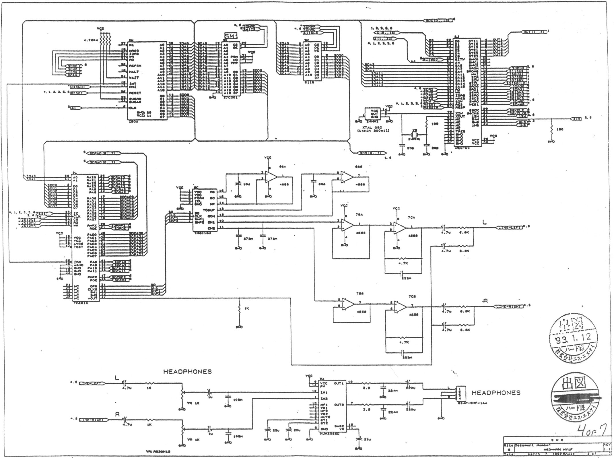
As you can see, the left and right channel get amplified first by the 4558 dual opamps and THEN they get summed with the YM2610.

Now, with that out of the way, I'd like to talk about the choice of using a couple of NPN transistors over the original opamps used in the MV-1FS board, the 4558s, which are still available and are quite cheap.
I know a lot of you may not care for 100% accuracy and just want to get stuff done (which is great!), but I'd like to reproduce the original audio output circuit since the parts used are still available.

This means that it will not be as easy as doing the original or MKL improved mod, since we'll be "copy-pasting" the entire circuit block you can see on the right of the YM3016 (which involves the use of 3 4558 opamps and a whole bunch of other components) onto a new board, but at least we're going to have the original ("authentic", if you prefer) circuit used in the stereo MVS boards.

I'm probably doing it since I have some spare time these days.

First step will be lifting YM3016's legs from 10 to 16, so I can wire them to the new audio output board, along with YM2610's leg 27 (because I don't have a MV-1FZ schematic and I don't trust the board) to tap the other signal and send it to the new board.

Note that we could have lifted only legs 10 and 11 from the YM3016 and leave the other 5 there. Those are used for biasing and buffering the chip and we could have left the C844G opamp doing that, but since we're here doing this, we might go down the rabbit hole all the way.

I'll post pics of the work in progress!


EDIT: some useful resources for those interested:

Schematics of (I believe) a Neo Geo MVS MV-1FS and an AES (courtesy of NeoGeoDev)
https://wiki.neogeodev.org/index.php?title=Schematics

Yamaha YM3016 DAC datasheet:
http://pdf.datasheetarchive.com/datasheetsmain/Datasheets-8/DSA-151908.pdf

Texas Instrument RC4558 Dual Operational Amplifier datasheet:
http://www.ti.com/lit/ds/symlink/rc4558.pdf

NEC C884G Quad Operational Amplifier datasheet:
http://pdf1.alldatasheet.com/datasheet-pdf/view/163079/NEC/UPC844G2.html
 
Last edited:

donluca

Ninja Combat Warrior
Joined
Aug 19, 2015
Posts
529
Alright, the board is ready

IMG_20150909_213859.jpg

it's been one hell of a job, I should have used a bigger breadboard. I'll fit the opamps and wire it to the Yamaha chip and fire this up and see what happens. (inb4 everything blows up)
 

donluca

Ninja Combat Warrior
Joined
Aug 19, 2015
Posts
529
Well, house didn't catch fire, I'm here still alive, and the new/old audio output stage is kicking!

The output level is still a tad quieter than my Saturn but it's absolutely acceptable and I can crank it up a lot without getting unwanted noise in the way, so all is good.

This said, putting the circuit in has been hell.

It's basically impossible lifting the pins of the Yamaha YM3016 without asking for trouble, so I've cut the traces going to the pins 10-16 under the board and removed the C884G opamp (which is useless now) and soldered the wires on the solder side of the board.
To remove the C884G just run a sharp knife on the soldered pins, lift it and gently bent it forward and back until it comes free.

Here's a pic of it, I'm probably going to glue the board to the side.

IMG_20150910_005043.jpg

If someone's interested in it, I can make a proper tutorial (and a better board design, mine is a mess and I'm surprised I didn't short anything).
 
Last edited:

GadgetUK

Ace Ghost Pilot
Joined
Sep 27, 2013
Posts
1,323
Never thought to look at this, but I can see you are onto something there. That probably explains why the FM output is quieter than the PCM output (I think?). I've always noticed that the FM music just seems to be maybe 20% or 30% lower than it probably should be. That said, I am using MKLs board there and it's much better than without. I might revisit this - it would be really cool if we could design a board for this I think and use SMD components to make it low profile.
 

donluca

Ninja Combat Warrior
Joined
Aug 19, 2015
Posts
529
It's definitely doable as the 4558 are still widely available from several manufacturers: Motorola, Fairchild Semiconductors, Texas Instruments and JRC (I think) are still producing them and are dirt cheap (I bought 4 of them + sockets for 1€ at my local electronics shop).

Doing this with SMD components means the board becomes tiny, but there's still the wiring issue. Cutting traces may be not everyone's cup of tea as well as carefully cutting pins and removing an SMD IC. Leave alone trying to desolder an entire IC without the proper tools.

IMHO, this is the only stereo mod that should ever be done to any MVS board, since it's the exact output stage used in the stereo MVS boards.
But I'm a purist, so yeah, I can definitely see people not wanting to go through the hassle and just do the basic channel summing circuit or MKL's mod.

I believe we can slightly simplify this using the quad opamp LM324 which has been used in more recent MVS boards (the 4 slot comes to mind) along with a single 4558 for buffering and biasing the YM3016.

Also, there's the option of doing a simpler mod leaving the C884G opamp doing the buffering and biasing, which means you only need two 4558 to amplify the two channel signal.
This way you just have to cut the traces from pin 10 and 11 of the YM3016 and solder a couple of wires to get left and right channel, along with +5V and ground.
Not sure if it would work 100% correctly and the resulting audio quality.

Anyway, I wouldn't recommend this stereo mod to anyone who doesn't have very good soldering skills, patience and a steady hand.
I almost screwed up in a couple occasion but thanks god I didn't do any damage.

Do you guys want a short recording?
 
Last edited:

GadgetUK

Ace Ghost Pilot
Joined
Sep 27, 2013
Posts
1,323
I guess a recording would be useful - just to compare volume levels of the FM vs PCM. Not sure what the best games to test with are?
 

donluca

Ninja Combat Warrior
Joined
Aug 19, 2015
Posts
529
I'm clueless when it comes to FM and PCM.

One thing I know for sure is that the MKL circuit needs to be fixed.

Here's the fixed version:

2v9vzb9.png

If you tell me which game/track you want to hear I can do it.

Meanwhile I can upload a track like Matrimelee's intro which doesn't have SFX in it if you want.
 
Last edited:

GadgetUK

Ace Ghost Pilot
Joined
Sep 27, 2013
Posts
1,323
What I am not sure about now is that channel 3 is not amplified my MKLs circuit? With regards to a game to test, I guess you need a game that uses all 3 channels - not sure which, I guess you could isolate each channel from output and see if there's sound coming through on each channel as you test each one separately, then reconnect them all and record the output.
 

donluca

Ninja Combat Warrior
Joined
Aug 19, 2015
Posts
529
If you look at the original MKL circuit (it's in my first post) you'll see that the third channel (I guess it's the FM one) gets summed to the other two channels (PCM I suppose) first, and then amplified along them by the transistors.

You can clearly see that the FM channel doesn't get amplified in the original MVS circuit, as it gets summed AFTER the two PCM channels have been amplified.

I'll do some research on the games audio when I have time, right now I really want to finish consolizing my MVS.
 

UDb

n00b
Joined
May 8, 2021
Posts
8
Very valuable info, thanks. Did you make a step by step tutorial for this mod ?
 

MKL

Basara's Blade Keeper
20 Year Member
Joined
Mar 8, 2002
Posts
3,686
I see this thread only now as I had long stopped watching the forum when it was posted. The allegedly fixed version of my circuit posted above is based on misunderstandings and incorrect assumptions which I'm going show.

The stereo circuit that commonly goes by my name and that the OP dismisses as "just the MV-1FS summing circuit, nothing new here" is in fact based on the first version of the home system (NEO AES revision) which has a better audio than the later revisions:

NEO-AES audio circuit.jpg

As can be seen, the left and right channels from the DAC go through two op-amps each before the analog channel from pin 27 of the YM2610 is added to them. At that point they take two different ways: to the headphone circuit where they remain stereo and to the A/V out where they are first mixed into a mono channel and subsequently amplified by a transistor. If we were to undo the mono mixing and restore stereo, the circuit would be like this:

NEO-AES stereo mod.jpg

And this is exactly the stereo mod I have proposed for the mono MVS boards that are meant to be consolized. Clearly the OP confused the amplification provided by the transistors at a later stage with that provided by the op-amps at an earlier stage.

On the MV-1FZ the only difference is that the left and right channels from the DAC go through one op-amp per channel instead of two. And it should be noted that the OP didn't realize that the op-amp connected to pins 12-15 of the DAC is already contained in the C844G and added it as part of his external mod: nonsensical.

audio circuit MV1FZ.jpg

According to the OP the MV-1FS has "the original ("authentic", if you prefer) circuit used in the stereo MVS boards". It turns out that MVS boards are in fact
different from each other: while on the MV1FS the L and R channels go through two op-amps each, on the 2-slot they go through three and on the 4-slot (and 6-slot) through four. So what's the authentic MVS circuit?

2-slot audio.jpg
MV4 audio circuit.jpg
But I find this point irrelevant anyway as I fail to understand why replicating the MVS circuit would matter when doing a consolized system considering MVS
boards are not designed for outputting audio for home use. The AES on the other hand is designed exactly for that and the circuit I proposed for consolizations replicates what you find on the AES.
 

UDb

n00b
Joined
May 8, 2021
Posts
8
Thanks for the clarification. I'm gonna build the mod based on your original scheme ;-)
 

MKL

Basara's Blade Keeper
20 Year Member
Joined
Mar 8, 2002
Posts
3,686
And if you want to have the missing op-amp you can do this:

Immagine.jpg
 

dragonpt

Over Top Auto Mechanic
10 Year Member
Joined
Oct 19, 2008
Posts
867
Very nice explanation MKL ( as always)

@Misos
Ye I have an similar issue with an 1fz , I'm also in doubt if all the original sound caps are needed after doing the stereo mod...
 

donluca

Ninja Combat Warrior
Joined
Aug 19, 2015
Posts
529
I'll go back to this at some point and reply properly because I don't remember what this all was about.

I only remember that at the time I wanted to add a proper Stereo Out for my MV1FZ, looked at MKL fix and found that the YM2610 was amplified twice or something which was obviously wrong and lead to the YM2610 being too loud, so I just fished out the schematics of an arcade 1-slot board which had stereo out and copy-pasted its output stage which had worked flawlessly and with correct audio balance so far.

When I have some free time I'll dig back into this and give a more through reply, but I can tell you straight away that I didn't care for making a "better" audio output or anything, I just wanted stereo out with correct audio balance between the audio chips.
All the MVS arcade boards, AFAIK, use the same audio chips, so it's just a matter of properly mixing and amplifying their outputs to line level.

EDIT: and just to make sure: this wasn't meant for a "consolization". It was only to add a proper line level stereo output to a MV1FZ. You can then get this stereo output and feed it to the stereo amp in your cab, whether it's a qsound amp or what have you.
 
Last edited:

UDb

n00b
Joined
May 8, 2021
Posts
8
Need some help: made the mod according to MKL's original design. Removed the 2 resistors on my MV1FZS and connected everything.
Getting only extremely low sound with tons of noise out of the custom PCB.
Interesting thing is that there still is original sound even with the 2 resistors removed ?!!
Any suggestions ?
Thanks
20210613_084055.jpg


20210613_084128.jpg
20210613_090010.jpg
 

UDb

n00b
Joined
May 8, 2021
Posts
8
Found out the C1815 pinout info was wrong and therefore mounted inverted.
Now placed correctly, I get sound but still lots of distortion/noise especially on left channel.
Any clues?
 
Top