Neo Geo AES rev1 - lower rating 4.25 on power transistor.

Tengugurl

Cheng's Errand Boy
Joined
Feb 9, 2017
Posts
111
Hi!
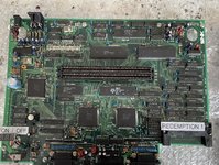
Trying to get a former AES parts console up and running again but running into a few issues

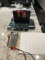
TL;DR - 4.1 v on the 7805 - psu by itself is measuring at 5.25v no load (rated at 5v 3A)

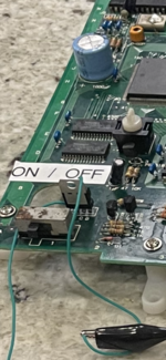
1) bought a 5v 3A psu reversed wires to be center negative
2) hooked up via RGB scart and retrotink 2x scart on flat screen panel (Aka my test bench tv)
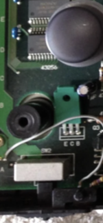
3) I added a 24mhz crystal to the rev 1 as I don’t have a daughter board (OEM)
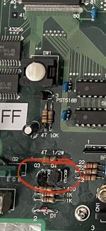
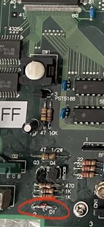
4) replaced the 7805 - few other missing parts
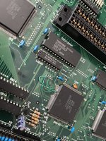
5) Installed a reset button, 43256 ram (fixed some trace damage) and Neo Pro-B0 had some leg damage, was able to solder and trace out lines


I read here:

That I may need to replace the caps as they most likely are dead. (That’s fine but curious if that might be why I can’t get anything to display)

Questions:
1) with no daughter board/24mhz crystal - told I can only do RGB - would RGB scart into a retrotink be okay? Or will I have sync issues as the refresh rate is tough for a flat panel?

A. Does this need to be on my pvm to work or rgb scart modded Consumer tv?

thanks all!
 

Attachments

  • BD8C26D8-001B-498A-8E76-18CA5721299F.jpeg
    BD8C26D8-001B-498A-8E76-18CA5721299F.jpeg
    1.9 MB · Views: 10

maki

Edo Express Delivery Guy
Joined
Jan 1, 2022
Posts
334
It can do RGB and Composite without the daughterboard, Composite might lose sync every now and then though (that was the purpose of the daughterboard, to sync the master clock to the Composite subcarrier, improving Composite, sacrificing RGB quality and other things), RGB should be fine

My LCD TV from LG can't work with the RGB input from 1st gen Neo Geo chipsets because of the slow and dirty SYNC (Composite works though), people use faster crystals (24.168 - 24.3) to increase compatibility with LCD TVs. My OSSC is still broken, spare parts take weeks if they get here at all, so I can't tell if that is going to work, the internet says it does.

There is a thread about the compatibility of Neo Geos with TV sets, the old models with the first gen are finicky.

I was not aware of a 7805 in any Neo Geo, you sure it was supposed to have one?
 

Tengugurl

Cheng's Errand Boy
Joined
Feb 9, 2017
Posts
111
Oh okay, I may give composite a go then and try a few TVs. Yeah I have seen a few revision 1 pcbs online with 7805s in them here is a pic of the one I installed and the green 7805 is from another pic off the forum.

Keep you posted about the composite test today. Trying it on a CRT, PVM and maybe another flat screen for good measure
 

Attachments

  • 398F0DF7-598A-498E-BD8D-E62B734A9E68.png
    398F0DF7-598A-498E-BD8D-E62B734A9E68.png
    13.6 MB · Views: 6
  • 7C6C249F-92B9-4201-815B-AF4E4C07949F.png
    7C6C249F-92B9-4201-815B-AF4E4C07949F.png
    9.6 MB · Views: 5

MKL

Basara's Blade Keeper
20 Year Member
Joined
Mar 8, 2002
Posts
3,686
The "green 7805" is in fact NOT a 7805, it's a transistor (2SB1135 if memory serves me well) as should be clear from the ECB marking.
 

Tengugurl

Cheng's Errand Boy
Joined
Feb 9, 2017
Posts
111
Well crap, I didn’t have a pcb that showed the model number so I read a few forums and thought I saw 7805.

Guess I’ll need to buy a few more parts

Hopefully I didn’t damage anything with the 7805
 

maki

Edo Express Delivery Guy
Joined
Jan 1, 2022
Posts
334
good chance IMO that’s nothing got damaged, the 7805 needs more than 5V to start working, worst case is that the 7805 is damaged ;)

there is two or three more transistors involved in the power circuit, right next to that "green" one
 

Tengugurl

Cheng's Errand Boy
Joined
Feb 9, 2017
Posts
111
Phew. Yeah I was only reading ~4v off it so phew well next time I go all ham on things and think I read something I’ll ask here as I don’t want to cause any issues :)

@maki
Would this work?

I thought I saw these on another picture as well:

I should probably just stick with the first link if that will work. From the data sheet online seems like it but want to double check.

Oh ps lucky me. Just noticed one of the Pro-B0 legs pin 10 was missing. Going to see if I can get my microscope out and do some micro soldering to keep from having to replace the chip
 

maki

Edo Express Delivery Guy
Joined
Jan 1, 2022
Posts
334
There was a post in a closed FB group where someone removed both daugtherboards (Video PLL and the one for the Power) on a first gen AES, I'll check the web, if I can't find it, I'll open mine and will give you the values/details on it

Pin 10 on the B0 is quite important

edit:
the internet says its a NEC A1442, so a 2SA1442 should work as substitute

its only purpose is to "get hot" if the 5V rail voltage rises above 5.4V
 
Last edited:

Tengugurl

Cheng's Errand Boy
Joined
Feb 9, 2017
Posts
111
Ahh thanks so much for sharing what the transistors do and further info on the model #.

Interesting, darn wish I had more info on the removal of the daughter boards. I’d so appreciate any pics you could take :)

Thank you!
Yeah my luck haha if it was pin 12-14 I’d be fine but I love a challenge.
 

maki

Edo Express Delivery Guy
Joined
Jan 1, 2022
Posts
334
Well there is my thread about that AES first gen:

but its was just about the video PLL daughterboard

you do not need that circuit IMO if you supply constant 5.0V, should be fine for testing what else is off, its a circuit that converts voltage higher than 5.4V to heat, stay at 5.0V and you won't need it (at first)

the circuit itself is described in the NeoGeoDev wiki, see my previous link, schematics and parts

so if you leave that transistor out and use 5.0V (less than 5.2V is recommended IIRC), you should be able to check for other problems, remember, that board was used as donor, lets hope you can fix the B0, hard to find, only in AES or MVS of the first gen
 

Tengugurl

Cheng's Errand Boy
Joined
Feb 9, 2017
Posts
111
I am having a lot of signal drop. I was able to find the original voltage reg. And pop it in and I am getting 4.25v + on the voltage regulator but when I take the psu off (5v 3A center neg.) I am at 5.24v+

TL; DR
Any tips? I’ll read up more but curious if anyone has run across a neo geo aes that won’t power up when you replace the voltage reg or a pcb that’s not going to 5v+


I need to read up on the wiki further but, curious what is in-line that is causing this. I’d assume it goes right from the psu barrel (which I read at 5.24v) to the voltage reg to step it down to 5v+ for all the components.

Even more strange still, I put in the replacement voltage regulators I bought (Aka the NEC 2SA1442) then I get nothing on the voltage reg. :(
Wondering if they are doa from eBay?
They didn’t have any continuity before I installed them (assume this is how you test a voltage reg.)

Btw got the reset button installed and the ram ICs etc….
Micro soldering was fun but I will def need a new Neo-Pro B0
 

Attachments

  • F4E5347F-62C4-4A46-883C-76DB1F63CB49.jpeg
    F4E5347F-62C4-4A46-883C-76DB1F63CB49.jpeg
    3.6 MB · Views: 12
  • 0A964D03-9976-4EE2-8593-1767586F56AC.jpeg
    0A964D03-9976-4EE2-8593-1767586F56AC.jpeg
    1.8 MB · Views: 11
  • 98629DBB-8DC5-405C-AE48-88DF4A1856B4.jpeg
    98629DBB-8DC5-405C-AE48-88DF4A1856B4.jpeg
    1.8 MB · Views: 12
  • 582C1F1C-21A0-4EF7-96D4-CA71209199C1.jpeg
    582C1F1C-21A0-4EF7-96D4-CA71209199C1.jpeg
    1.9 MB · Views: 11

maki

Edo Express Delivery Guy
Joined
Jan 1, 2022
Posts
334
its sounds like you have a short somewhere

check the other two transistors, the diode and the resistors from that overvoltage protection circuit

NEC 2SA1442 is a power transistor, its only purpose is to "burn off the excess voltage if it rises over 5.4V", that circuit can be removed and it should not affect the operation

these first AES rely on a external regulated PSU, some of these AES got the overvoltage protection, some don't

edit:
do you have another 5V PSU center negative for testing?
 
Last edited:

Tengugurl

Cheng's Errand Boy
Joined
Feb 9, 2017
Posts
111
You rock! Thanks for your ideas/help :)
Excited to try this suggestion out.

I do have another psu to try and it same thing, not getting any voltage on the NEC 2SA1442 power transitior.

Sorry to sound super naive but, are these two things transistors? I assume they are.

To test them, is it true that it’s best to remove them from circuit?

Quote on how to test:
Remove the transistor from the circuit for accurate test results. Hook the positive lead from the multimeter to the to the BASE (B) of the transistor. Hook the negative meter lead to the EMITTER (E) of the transistor.
Use a low ohms scale setting on a multimeter( I have a fluke 101)


Check the base to collector readings in both directions. Touch one lead from the meter to the base lead and the other to the collector lead. Look at the reading, then reverse the leads. A good reading will show infinity in one direction and give a reading of about 600 in the other.

Check the base to emitter readings in both directions. Touch one lead to the base and the other to the emitter. Check the meter and reverse the leads to read the opposite direction. Good readings should show infinity in one direction and close to 600 in the other.

Replace a transistor if either the base to emitter or base to collector readings show zero in both directions or infinity in both directions. Zeros reveal a short while infinities indicate an open diode within the transistor.

(Achievement unlocked lol think I learned how to test a transistor - sorry just love learning things)

If I need to replace them Do you know a part number? I can’t seem to find one online.

I see something called a zener diode? And a pnp transistor b1135 (but I can’t find one that has that half circle shape)
Sorry phone is being dumb. I’ll take a look at mine see if I can find a part number
 

Attachments

  • 5C9B7531-CC0F-483F-9369-A174AAF15526.jpeg
    5C9B7531-CC0F-483F-9369-A174AAF15526.jpeg
    593.4 KB · Views: 5
Last edited:

Tengugurl

Cheng's Errand Boy
Joined
Feb 9, 2017
Posts
111
Oh and this is probably the diode ?
 

Attachments

  • 82C06E63-5EB8-4E3C-94D6-42C01EC133D7.jpeg
    82C06E63-5EB8-4E3C-94D6-42C01EC133D7.jpeg
    592.8 KB · Views: 8

maki

Edo Express Delivery Guy
Joined
Jan 1, 2022
Posts
334
this is really hard when you're doing it for the first time

there is a schematic even with the part numbers on it :)

the section "overvoltage protection"

here is just the schematics:

"Q2" is the big green power transistor (you keep calling it voltaqe regulator but its not ;) )
they didn't bother putting a part number on that one, it really just turns over-voltage to heat

D1 the Zener diode is a 5.6V one, datasheet: https://datasheetspdf.com/pdf-file/1221657/Rectron/BZX55C5V7/1
check if it is short form both directions with the diode or continuity to tester on the multimeter

Q4 is a BC546BP, Q3 a 2SC639

have you tried with another PSU?

tbh, I test transistors for shorts only, but if you have a transistor tester on your multimeter, go for it
 

Xian Xi

JammaNationX,
15 Year Member
Joined
Dec 1, 2005
Posts
27,750
A lot of times in my experience where there is significant voltage drop on the early systems, it is due to a bad 0.01uf cap that is soldered to the power jack under the motherboard.
 
Top