CPS2 Black board Revival (What am I doing wrong?)

Lemony Vengeance

Mitt Romney's Hairdresser,
Joined
Jan 30, 2012
Posts
4,204
ok, got the Eeprom programmer (a Wilhelm GQ-4X) along with the 42 pin adapter. now I just need to select which device I want to read from.. What model # of mask roms did capcom use for the black boards? I cant see on these chips..
 

Xian Xi

JammaNationX,
15 Year Member
Joined
Dec 1, 2005
Posts
27,750
ok, got the Eeprom programmer (a Wilhelm GQ-4X) along with the 42 pin adapter. now I just need to select which device I want to read from.. What model # of mask roms did capcom use for the black boards? I cant see on these chips..

I don't even know if that programmer can read 64mbit roms.
 

Xian Xi

JammaNationX,
15 Year Member
Joined
Dec 1, 2005
Posts
27,750
Hopefully it has the same pinout of the roms you have.
 

Lemony Vengeance

Mitt Romney's Hairdresser,
Joined
Jan 30, 2012
Posts
4,204
ok, progress, the two mask roms in the 15 and 19 sockets are PD23C64020 (page 04-37).. not sure about the ones in 11, 13 and 17
 
Last edited:

bustedstr8

Trollbox Trade Federation,
Joined
Oct 15, 2007
Posts
943
Going by the specs from a regular board there is 64Mb of Qsound data and 256Mb of grafx data....the chips should all be be 64Mb.
 

Lemony Vengeance

Mitt Romney's Hairdresser,
Joined
Jan 30, 2012
Posts
4,204
Hmm if I don't have the means to dump these roms and I'll have to re-populate it with the standard 32 Mbit roms, I may just convert it into a Hyper anniversary board for my personal use. That, or an MvC. The jumpers will need to be changed up though.
 

Dion

Known Scammer, NeoGeoFreak Co-Founder
Joined
Aug 24, 2000
Posts
2,070
Have you tried reading all of the 64mb roms with the same settings?
 

bustedstr8

Trollbox Trade Federation,
Joined
Oct 15, 2007
Posts
943
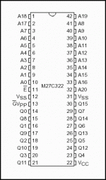
You could read the high and low halves as 27c322 if you set A21 manually using a socket and jumper wire.
 

Dion

Known Scammer, NeoGeoFreak Co-Founder
Joined
Aug 24, 2000
Posts
2,070
You could read the high and low halves as 27c322 if you set A21 manually using a socket and jumper wire.

And if you do that you can simply compare against the 32mb MAME files.
 

bustedstr8

Trollbox Trade Federation,
Joined
Oct 15, 2007
Posts
943
I found a pinout for a MX 64Mb mask rom and they used pin 11 as A21. Hopefully NEC does the same.

Get a 42pin socket and lift up pin 11 and solder a wire to it. Then solder the wire to Vcc to read the high half of the rom and then to Vss to read the low half. These files should match up to something on Romident.
http://romident.coinopflorida.com/

m27c322.gif
 

Dion

Known Scammer, NeoGeoFreak Co-Founder
Joined
Aug 24, 2000
Posts
2,070
Ok. I'm trying to figure out how to identify the part number of these mask roms to dump my 64mb MVC roms. The numbers on top of the chip don't pull up in google or the programmers list. I have a Topmax2 which is a very expensive programmer. I'm guessing the numbers on the chip are Capcom's. Where did you pull PD23C64020 from? All of mine start with LHMN and in your picture it looks like yours do also.
 

Lemony Vengeance

Mitt Romney's Hairdresser,
Joined
Jan 30, 2012
Posts
4,204
Ok. I'm trying to figure out how to identify the part number of these mask roms to dump my 64mb MVC roms. The numbers on top of the chip don't pull up in google or the programmers list. I have a Topmax2 which is a very expensive programmer. I'm guessing the numbers on the chip are Capcom's. Where did you pull PD23C64020 from? All of mine start with LHMN and in your picture it looks like yours do also.

here's a pic:

temporary_zps052352ec.jpg
 

Dion

Known Scammer, NeoGeoFreak Co-Founder
Joined
Aug 24, 2000
Posts
2,070
Ok. I see. Mine all have the LHMN beginning.
 

Lemony Vengeance

Mitt Romney's Hairdresser,
Joined
Jan 30, 2012
Posts
4,204
I'm a bit hesitant to do this because I'm not sure where to solder the wire for Vss and Vcc. From your illustration, I would imagine it's pin 12 for Vss and pin 22 for Vcc, correct?

I found a pinout for a MX 64Mb mask rom and they used pin 11 as A21. Hopefully NEC does the same.

Get a 42pin socket and lift up pin 11 and solder a wire to it. Then solder the wire to Vcc to read the high half of the rom and then to Vss to read the low half. These files should match up to something on Romident.
http://romident.coinopflorida.com/

View attachment 9603
 

bustedstr8

Trollbox Trade Federation,
Joined
Oct 15, 2007
Posts
943
I am not very familiar with the Willem adapter boards, but you might find some headers on it you could use for the high and low signal.
It doesn't matter where you tap the +5V and 0V from as long as it remains steady during the chip read. You could solder direct to the chip if you wanted.
 

Attachments

  • IMG_0386[1].JPG
    IMG_0386[1].JPG
    1.6 MB · Views: 66
Last edited:

Lemony Vengeance

Mitt Romney's Hairdresser,
Joined
Jan 30, 2012
Posts
4,204
I am not very familiar with the Willem adapter boards, but you might find some headers on it you could use for the high and low signal.
It doesn't matter where you tap the +5V and 0V from as long as it remains steady during the chip read. You could solder direct to the chip if you wanted.

I was thinking of doing just this. I'll do it tonight.

*EDIT*

Ok, done but I don't think it worked.. here's what I got when I uploaded the dumps in BIN format:

2013-12-29_2100.png


Heres what I got when I uploaded them in HEX format

2013-12-29_2106.png


This is the case with all the roms. I can provide the rom dumps I made (not sure if I did them right, either..)
 
Last edited:
Top