Consolization using Neo CD Controller Board

dalde1

n00b
Joined
Nov 5, 2011
Posts
40
OK, so finally got round to try and complete this..

Video, Power and sound all sorted so onto the final step of the controller board, I'm consolizing in a CD shell.

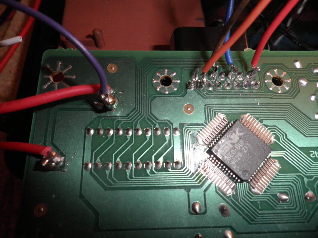
Power going via the switch OK to all points on the controller board but having problems getting the controllers working, On the top of the board it says pin 1 on the right which is opposite what you would expect. I have tried a couple of controls but no joy. Presumably I don't need to send power to pin 8 as is already supplied to the board, question I have does it need a ground anywhere or any other connections I'm missing ? (Xian ;)) ?. I've attached a couple of pictures of the 2 controller ports and where the power is coming from etc.

Thanks in advance for any help and advice

Dave

Controller1.jpg


Controller2.jpg
 
Last edited:

DanAdamKOF

Iori's Flame
20 Year Member
Joined
Jun 15, 2002
Posts
8,250
Are you saying you don't have a ground wired to it?... yeah you'll need that.
 

DanAdamKOF

Iori's Flame
20 Year Member
Joined
Jun 15, 2002
Posts
8,250
Yeah, sorry if I'm stating the obvious, but your input signals work by closing a circuit, and in order to close that circuit you need ground to pull the line low. Without ground you can press buttons as much as you want, but there's no "other side" to them lol.

Tie whichever pin on the pinout is specified as ground (I don't have it handy) to ground from your power supply somehow. I'd normally assume that the board that the controller ports is on should already have a connection to ground somewhere, but since it's been hacked to bits for the CMVS retrofit I don't think we can be sure of it, so I think you should just run ground to it outright.

Mind you I've never been inside a NGCD so I can't really speak for how the board is laid out, I'm just going off of basic electrical theory here.
 
Last edited:

dalde1

n00b
Joined
Nov 5, 2011
Posts
40
Cheers Dan

Will give that a go tomorrow, let you know how it goes

Thanks

Dave
 

Xian Xi

JammaNationX,
15 Year Member
Joined
Dec 1, 2005
Posts
27,750
On the NeoCD controller board, SNK fd up and labeled it backwards.

If you are looking at it from the bottom like in the pic it is:

--9--10--11--12--13--14--15
1---2---3---4---5---6---7---8
 

dalde1

n00b
Joined
Nov 5, 2011
Posts
40
Thanks Xian

That's what I originally thought by looking at the pins and how I wired it up originally with the ground on pin 1 but it did not boot like that, do I need anything else ?. I'll try that again later and see what happens.

Cheers

Dave
 

dalde1

n00b
Joined
Nov 5, 2011
Posts
40
Confused now what could be the issue, tried connecting ground to pin 1 on controller 1 again and when try to power on cuts the power from the PSU out

Any ideas ?
 

Xian Xi

JammaNationX,
15 Year Member
Joined
Dec 1, 2005
Posts
27,750
You have a short somewhere. Double check your other wiring to the board.
 

dalde1

n00b
Joined
Nov 5, 2011
Posts
40
Grrr, this is going to be frustrating, disconnected all wires apart from via the power switch, as soon as connect ground to pin 1 on either player 1 or player 2 shorts out, I'm thinking must be a faulty controller board, not sure if there is a way to test or I suppose could try and clip the pins and connect via the normal method ?
 

dalde1

n00b
Joined
Nov 5, 2011
Posts
40
thanks Xian, the swicth works ok on its own, what should the switch wiring look like ? I'vce disconnedted the 2nd wire from the output which I had going to the rgb power in case that m,ade a diff but still the same
 

Xian Xi

JammaNationX,
15 Year Member
Joined
Dec 1, 2005
Posts
27,750
Can you snap some pics and tell me what your wiring is. It's possible you are wiring the switch wrong. Use a multimeter and check if pin 8 or pin 1 has continuity to the switch.
 

dalde1

n00b
Joined
Nov 5, 2011
Posts
40
Xian

The wiring to the switch is on the 1st pic in the thread, I have the 5v from the psu going to the wire on the bottom left then the power from the pin on the other side of the trace to the mv1c. I'll get the board back out in a sec and try to check the continuity

Thanks

Dave
 

Xian Xi

JammaNationX,
15 Year Member
Joined
Dec 1, 2005
Posts
27,750
Then do it opposite. +5v to board and ground to switch.
 

dalde1

n00b
Joined
Nov 5, 2011
Posts
40
Cheers Xian, aplogies for the dumb question but obvuiously im no electrician !. 5v from the barrell jack direct to the mv1c and ground to the cd controller board like how i've currently got it wired and then connect the controller pins as normal with the 5v and ground ?. Hopefully thats right, I'll try it when get back from work !

Thanks again

Dave
 

Xian Xi

JammaNationX,
15 Year Member
Joined
Dec 1, 2005
Posts
27,750
Yup, so instead of breaking the +5v line you are breaking the ground with the switch.
 

dalde1

n00b
Joined
Nov 5, 2011
Posts
40
Thanks Xian !, hooked up with the ground going through the switch and works perfect, also the LED on the controller board works now also which is another added bonus

Cheers

Dave
 

dalde1

n00b
Joined
Nov 5, 2011
Posts
40
D Button Controller 2

Another one for Xian I think !

Nearly completed this apart from ad odd problem with Button D on controller 2, when in the I/O menu with just Player 1 plugged in then all shows's 0's and tests OK, when plug player 2 in all buttons work apart from button D with then shows as 1 like its switched on, connection seems to test OK with multimeter, any ideas ?, so close its driving me mad !

Cheers
 

Xian Xi

JammaNationX,
15 Year Member
Joined
Dec 1, 2005
Posts
27,750
Trace the pin, make sure it isn't touching ground anywhere.
 

dalde1

n00b
Joined
Nov 5, 2011
Posts
40
Thanks Xian

I have tested the ground on the jamma harness connections and nothing, I have resoldered the wire to make sure all clean and still the same, do you think is likely to be on the controller board end ?, if so I can't work out how as pin 4 no way near the ground, is there any other way its conencted ?. Also I'm getting random interference, I;ve got a 75 ohm resistor on the sync, does this need to be higher or do you think shielded better ?

Cheers

Dave
 

Xian Xi

JammaNationX,
15 Year Member
Joined
Dec 1, 2005
Posts
27,750
There might be resistors tied to some of the controller pins, I'd remove them since they are superfluous. Since you are only using the board for the controller ports and not the controller logic they aren't needed. The control signals are usually held high and those resistors might be grounding them.
 

dalde1

n00b
Joined
Nov 5, 2011
Posts
40
Done it !!!

Thanks Xian, All works perfect now !!, removed the resistors which sorted out the D button issue, put a 3.2 Kohm resistor on the sync so solid as a rock now on my plasma and 180ohm resistors on the R G * B lines.

Thanks again for all your help on this, definately couldn't have done it without the time you have taken to answer my questions

Cheers

Dave
 

Xian Xi

JammaNationX,
15 Year Member
Joined
Dec 1, 2005
Posts
27,750
No problem dude. I've been through it when I made my Alien CMVS from a Neo CD. I was going to do the exact same thing but since I was smoothing the top of the shell I didn't need the power button at that location any more.

attachment.php

attachment.php


Here's the album with some other pics:
http://www.neo-geo.com/forums/album.php?albumid=47
 
Top