Funny issues w/ MVS cab

Billkwando

OG OG,
20 Year Member
Joined
Aug 14, 2000
Posts
1,768
I just got a 1 slot cab from a friend, and it has a wacky issue.

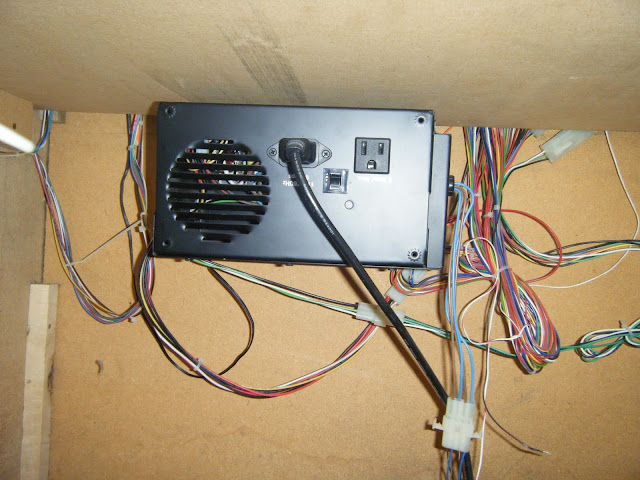
You have to unplug it to turn it off/on.

The cab itself is a Dynamo HS-5, and it has the (broken off but still working) toggle switch on the top, but when you switch it off, only the monitor turns off, and the MVS board keeps right on going, sound and all. Wtf?

It also seems to have the internal speakers disconnected. I'm not quite sure what to do about that, but my friend used to keep a single stereo speaker on top of the cab (sideways), with a wire running in through the back with 2 alligator clips clipped to the pins on the speaker/headphone connector. He gave me the speaker with the cabinet, so I hacked a 4pin floppy connector off of an old PSU and alligator clipped to that instead, so now it just slides right on to the connector with no fussy shorting issues. It looks and sounds fine (prolly better than the cab speakers would) but I'm still curious about how to get the whole thing running as stock as possible, just so I have that option.

Lastly, the plexi is riveted on to the cp, and somebody used some hideous stick-on letters for the ABCD on the overlay, and I'm wondering how hard it would be to fix that up.

It's clearly a beater cab, with scratched up sides and no side art, but from the front it looks great (minus the cp) and the 25" monitor is beautiful.

Suggestions?


Here's a vid of it (next time I'll remember that holding the screen up to your eyes = breathing on the mic, but I was kind cramped and wanted to get as much as I could in the frame):


Edit: Oh durr... I forgot to mention the biggest issue. It's randomly rebooting games. The monitor doesn't power down, it just jumps to the green jumblescreen, then the Neo Geo logo.

Edit 2: This is a fascinating thread. I think I'll finally have to break down and buy a multimeter:
http://www.neo-geo.com/forums/showthread.php?t=18784&highlight=random+reset
 
Last edited:

grips03

Krauser's Shoe Shiner
Joined
Sep 10, 2004
Posts
240
Sounds like cabinet is not wired right. I would recommend you re-wire either the power supply and monitor. Don't forget to keep using the iso transformer. Or re-wire the whole thing (jamma and power) so it makes sense to you. Jamma is mono, so I would think you cabinet has single 8ohm speaker, but not sure on US Neo-Geo cabinets.

This is helpful site to review for basic hardware setup.

http://www.jammaboards.com/jcenter.html
 

Billkwando

OG OG,
20 Year Member
Joined
Aug 14, 2000
Posts
1,768
Sounds like cabinet is not wired right. I would recommend you re-wire either the power supply and monitor. Don't forget to keep using the iso transformer. Or re-wire the whole thing (jamma and power) so it makes sense to you. Jamma is mono, so I would think you cabinet has single 8ohm speaker, but not sure on US Neo-Geo cabinets.

This is helpful site to review for basic hardware setup.

http://www.jammaboards.com/jcenter.html

I know it's not wired right, I just can't figure out how, if the monitor and mvs board are wired to the same power supply, how one is affected by the switch and the other isn't.

I also got a multimeter to deal with possibly adjusting the voltage, but I don't understand how you only adjust the 5v without adjusting the monitor power, and I'm worried about jacking something up. I only got the cab yesterday, after all. I have zero experience with them.
 

shadows

Mature's Make-up Artist
Joined
Apr 18, 2010
Posts
1,352
You adjust the 5v on the psu, the monitor runs off the mains/~120v AC.
 
Last edited:

Billkwando

OG OG,
20 Year Member
Joined
Aug 14, 2000
Posts
1,768
You adjust the 5v on the psu, the monitor runs off the mains/~120v AC.

Aha! So that's solved, then the issue with the switch is that the power supply isn't connected to it. Guess I better research how to fix that.

On the speaker issue, would it hurt if I flipped the stereo/mono switch to stereo and turn it on? I thought I read on the boredstu site something about it playing stereo through "edge connector" (jamma?) if the switch was turned on? That sounds wrong though.
 
Last edited:

Billkwando

OG OG,
20 Year Member
Joined
Aug 14, 2000
Posts
1,768
Looks like my backwards-ass power supply isn't adjustable anyway...

DSCF0302.jpg


https://picasaweb.google.com/Billkwando/Mvs#
 

arakissun

Overtop Pathfinder
Joined
Nov 28, 2009
Posts
105
I think it's adjustable.Just see next to red bulb:)-the white adjustable pot.You must have tool to see the voltages,don't do it without it.
And your power cabel is not connected to PSU-the two AC
 
Last edited:

Billkwando

OG OG,
20 Year Member
Joined
Aug 14, 2000
Posts
1,768
I think it's adjustable.Just see next to red bulb:)-the white adjustable pot.You must have tool to see the voltages,don't do it without it.
And your power cabel is not connected to PSU-the two AC

Bwahahaha I see the white knob now, thanks! It sucks they mounted it facing the transformer though....gonna make it a huge pain to test and adjust without electrocuting myself. I did pick up a radio shack multimeter, lol.

When you say the power cable isn't attached to the AC, do you mean the actual power cable, or the switch?
 

topher

Tesse's Maintainence Man
Joined
May 8, 2004
Posts
2,904
Bwahahaha I see the white knob now, thanks! It sucks they mounted it facing the transformer though....gonna make it a huge pain to test and adjust without electrocuting myself. I did pick up a radio shack multimeter, lol.

When you say the power cable isn't attached to the AC, do you mean the actual power cable, or the switch?

In your pic, you don't have AC power going to your power supply. Did yiou disconnect it?

Also, your pwer supply only has one screw holding it down on the side opposite the xformer. Should be really simple to pull out.

Get some cab speakers and make that cab right.

Adjustment pot is at the bottome of the PSU as already stated.

If the switch is only killing power to the monitor, then PSU isn't tied into switch. Monitor runs off AC, rest of cab off DC from PSU --> generally AC line in to switch, down to filter then splits to monitor Xformer and PSU.
 
Last edited:

Billkwando

OG OG,
20 Year Member
Joined
Aug 14, 2000
Posts
1,768
In your pic, you don't have AC power going to your power supply. Did yiou disconnect it?

Also, your pwer supply only has one screw holding it down on the side opposite the xformer. Should be really simple to pull out.

Get some cab speakers and make that cab right.

Adjustment pot is at the bottome of the PSU as already stated.

If the switch is only killing power to the monitor, then PSU isn't tied into switch. Monitor runs off AC, rest of cab off DC from PSU --> generally AC line in to switch, down to filter then splits to monitor Xformer and PSU.

Nope, I didn't disconnect it, and the whole thing powers up just fine when plugged in. I see what you mean about the screw. Those terminals are gonna be hot though, right? I'm kinda wondering how to turn that knob (if needed) and keep the multimeter connected at the same time....unless I'm just supposed to jam the ends up into the quick connects or something. Also wondering how to turn the knob at all (safely). I assume as long as I'm not touching 2 of those screws at the same time, I should be fine?

Also, I have no idea where any of those wires attachd to the psu are going. In line with my earlier question, if I have to up (or lower) the 5v power, isn't it going to affect all that other mysterious stuff that's hooked up too (I assume it's just the lamp, which has a dead bulb)?


(bonus questions, what's "FG", and why are there 2 wires hooked to the 5v?)

Edit: According to this drawing, "AC" is the power going INTO the power supply, so does that mean this psu isn't hooked up to anything?

Edit 2: The light on the psu is on.
 
Last edited:

topher

Tesse's Maintainence Man
Joined
May 8, 2004
Posts
2,904
What are the bottom posts on the PSU labeled as? Couldn't really tell from the pics.
 

grips03

Krauser's Shoe Shiner
Joined
Sep 10, 2004
Posts
240
As pointed out earlier the AC leads going to the power supply are not there. But you say it powers up ok, perhaps it powers up after you reconnect them?

Might want to draw out on paper what is connected to what. Usually AC from wall goes to 3 prong power cord, then into AC socket with an IEC connector, then into power switch, fuse, EFI, then AC distribution point.

1- to ISO transformer (if equipped) and then onto the monitor.
2- AC terminals on the power supply
3-florescent light ballast

My cabinet is all metal and it connects to earth ground, but perhaps the wood ones have grounding blocks.
 

Billkwando

OG OG,
20 Year Member
Joined
Aug 14, 2000
Posts
1,768
As pointed out earlier the AC leads going to the power supply are not there. But you say it powers up ok, perhaps it powers up after you reconnect them?

Just to be perfectly clear, those photos you see in my previous post were taken with the power supply powered up. You may even be able to see that the red light is on. I think the case must be mislabled, cos otherwise it doesn't make any sense (so far). Kinda scary.


(while unimportant, my marquee light is a screw-in 15 watt lightbulb. The regular kind.)


Edit: I just watched the video below, and from it, and what I just noticed, I think the 5v15A and GND posts are my AC. Looks like the red & white wires are going straight from the transformer to the 5v15A post, and the green one is going to GND..

 
Last edited:

shadows

Mature's Make-up Artist
Joined
Apr 18, 2010
Posts
1,352
Would I test the 5V1A or the 5V15A?
The 5V1A is actually -5V not the same as 5V15A which is +5v. But you test on the jamma edge anyway not on the PSU outputs.

AC most be coming from somewhere else then, the PSU wouldnt power on otherwise.
 

Billkwando

OG OG,
20 Year Member
Joined
Aug 14, 2000
Posts
1,768
The 5V1A is actually -5V not the same as 5V15A which is +5v. But you test on the jamma edge anyway not on the PSU outputs.

AC most be coming from somewhere else then, the PSU wouldnt power on otherwise.

See my prev post. I think it's in the wrong case for the psu inside. Starting to look like a total hackjob.

BTW, every place I've read or seen says to test the actual posts, and at least one said to do it while the game is running. Weird.

Should I set my multimeter range to 200v and just start poking stuff? (prolly not cos I'm not sure which is ground) I just got over my noob fear by sticking my probes in an outlet strip just now. I'm no longer a multimeter virgin. Testing from the jamma connector does seem like the safest way.
 
Last edited:

shadows

Mature's Make-up Artist
Joined
Apr 18, 2010
Posts
1,352
Ugh that would be extremely stupid if that is the case. Not labeling anything like that.
Follow the wires, see where they go on the jamma edge and you can label those. Do the same for the AC.

No you dont want to test AC with the multimeter set on DC or vice versa.
And you want to test on the jamma edge to get accurate readings. Wire depending on gauge and length has a certain amount of resistance.

I think youd be better off just buying a new PSU and redoing the whole wiring for the power at least. They are like 25$ or so on jammaboards.com
 

Billkwando

OG OG,
20 Year Member
Joined
Aug 14, 2000
Posts
1,768
Ugh that would be extremely stupid if that is the case. Not labeling anything like that.
Follow the wires, see where they go on the jamma edge and you can label those. Do the same for the AC.

No you dont want to test AC with the multimeter set on DC or vice versa.
And you want to test on the jamma edge to get accurate readings. Wire depending on gauge and length has a certain amount of resistance.

I think youd be better off just buying a new PSU and redoing the whole wiring for the power at least. They are like 25$ or so on jammaboards.com

Do I want to touch the probes to the board, or disconnect the board and stick them in the harness? Also, wtf is up with those resistors on the psu, do ya think?
 

shadows

Mature's Make-up Artist
Joined
Apr 18, 2010
Posts
1,352
To the board, you want to have a load on the PSU otherwise the readings are pointless without a board connected.

And I have no idea what those resistors are for.
 

Billkwando

OG OG,
20 Year Member
Joined
Aug 14, 2000
Posts
1,768
To the board, you want to have a load on the PSU otherwise the readings are pointless without a board connected.

And I have no idea what those resistors are for.

Thanks a lot man. :)

Shit just got weirder. I tried to test & adjust, test & adjust, but no matter what I did, the voltage hovered around 4.7 volts. Ended up with the knob starting on one side and ending up turned all the way up.

Then, when I was going to latch it back up, I saw something funny. I was so distracted I caught my first control panel in the head (don't plan on doing that again!).


DSCF0321.jpg


Yeah. Hmm. Um...

So my cab has 2 power supplies, both of which are connected, and doing....something.
 
Last edited:

Billkwando

OG OG,
20 Year Member
Joined
Aug 14, 2000
Posts
1,768
Theres two PSU in there? :spock:

Apparently! Dunno where they're going or what they're doing! The power cord in that pic is obviously the one I have to unplug (from the wall) to turn the machine off.
 
Top