Advice about consolized systems

lscolman

n00b
Joined
Dec 7, 2009
Posts
28
Hi,

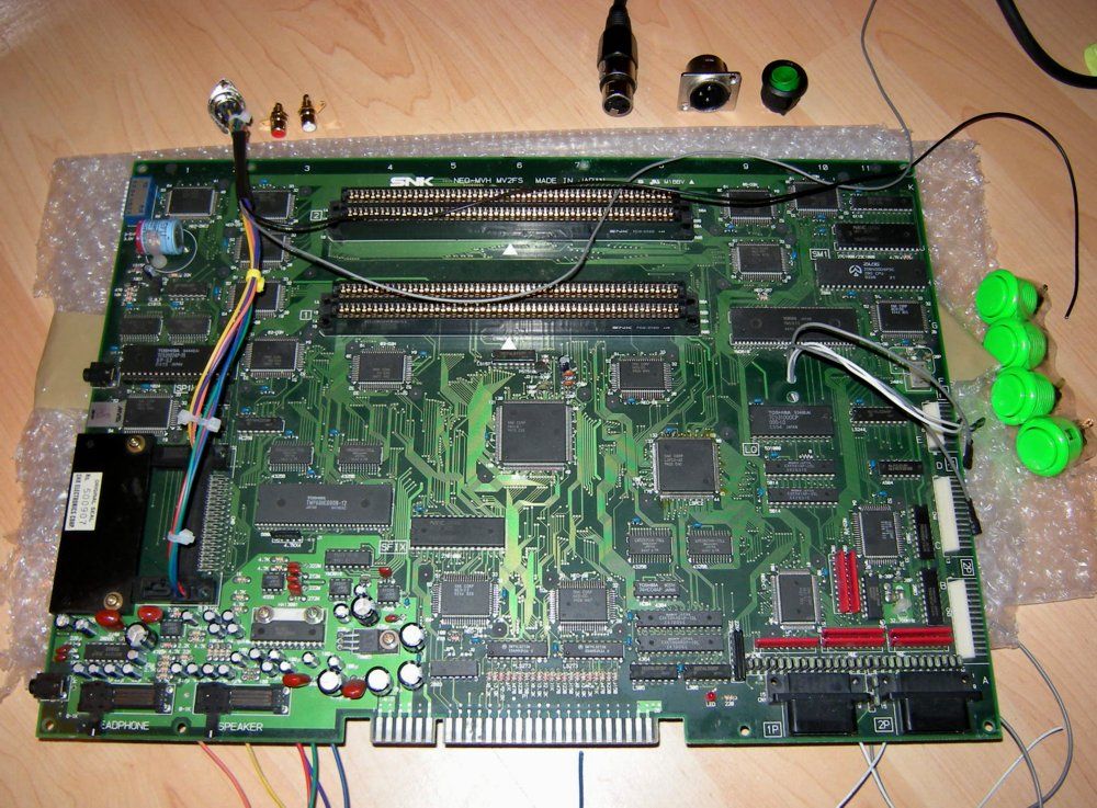
Having looked about a bit at the various consolized builds on ebay and on here, I wonder if it is really as simple as it looks?

JOYSTICK CONTROL
If I bought an MVS motherboard, such as the MV-1 or MV-1F, those boards have the joystick ports already present.

VIDEO
Could I take a tap from the Red, Green, Blue, Sync and Vid Ground Jamma pins to a Scart cable to handle the video

SOUND
The above two motherboards have headphone output jack. I could use a Minijack to 2 phono to handle stereo sound.

POWER
Connect a power connector to the appropriate pins on the Jamma connector and purchase an appropriate power supply? Need help locating something suitable.

BIOS
Both boards have socketed BIOS, so I could easily replace this with a UniBios v3.0.

Have I missed anything, or does this sound like it could work?

Thanks in advance.

Cheers, Lee
 
Last edited:

max-ng

Instructions? Pfft. I don't need them.... oh... fu
Joined
Nov 23, 2009
Posts
76
Hi Lee, just working on my 2 slot at this very moment - in the UK too. If you have ever soldered or made your own scart leads etc it is relatively easy - just take your time and plan carefully.

The 2 slot is easiest and the best board as it has a memory card slot, 2 joystick ports, headphone and amplified speaker out jacks and a socketed bios.

Basically you use the joystick ports for NG sticks (obviously!).

For a power supply use a PC ATX supply - I won a brand new one on ebay UK for .99p! The 12v and 5v and ground from the power supply goes to the board via your choice of plug (I'm using a 3 pin XLR). Then to a DPST switch and through seperate fuses to the board.

Use a standard 8 pin DIN for the video out. Wire as follows to give beautiful RGB (the RGB from a MVS is the best RGB I have seen of any 'console'):

http://www.mmmonkey.co.uk/console/sega/md-stereo-scart.htm

But take R audio to DIN 7 and left audio to DIN 1 - you now have stereo to your TV through Scart but can also tap the signals and add phonos to the rear case too - I'm doing this from the amplified stereo so I can direct this straight to speakers.

Add four buttons (any momentary type - I'm using Sanwa) for TEST, COIN 1, COIN 2 and SELECT (up or down) and wire to respective points on board.

That's about it - I have been trawling the web for a fortnight but these are some of the most helpful links:

http://www.engadget.com/2006/11/28/how-to-consolize-an-arcade-game/

http://www.jamma-nation-x.com/jammax/cmvs2slot.html

http://www.neo-geo.com/wiki/index.php?title=How_to_Consolize_an_MVS_Board

http://www.multimods.com/sgun.html
 
Last edited:

Xian Xi

JammaNationX,
15 Year Member
Joined
Dec 1, 2005
Posts
27,762
If making a RGB>SCART connection with an MVS board you might have to put 82ohm resistors inline for the RGB signals unless your TV can turn down the input a bit. The picture might be a little bright for some TVs at full voltage.

Also for power all 1 slots and 2 slots only need +5v to run, some need a small mod but it helps keeping it clean without having a big clunky PSU.
 

max-ng

Instructions? Pfft. I don't need them.... oh... fu
Joined
Nov 23, 2009
Posts
76
Xian Xi will have forgotten more about this than I will ever know (read a lot of his posts on 'consolization' searches lately) but as he says you only need the 12v for the amplifier and even this can be bypassed. I decided to keep it for simplicity and to provide a source for a cold cathode. :)

One thing I have learnt and this is after years of making scart leads and running my SFC, PCE, MD, Saturn, N64, DC and AES via RGB scart is that the MVS is the first 'console' I have that ever needed the +3v to pin 16 of Scart - never had to run that before but for some reason the MVS-2F needs it.

The pic is a touch bright but still debating whether to go with the resistors or not...

On the power supply I did use a mini one and rewire it from inside so just the main wire comes out.

mv1.jpg


Here is a pic of work in progess as of today (and an idea of layout) - hardest thing was finding a place to lead the wires neatly to the solder points under the board:

mv2.jpg
 

lscolman

n00b
Joined
Dec 7, 2009
Posts
28
Hi Max and Xian,

Thanks for the replies. I'm now actively looking to get a 2 slot board. Max, any more progress on the build? I'll probably bend your ear once it's done, and blatently copy your work! Pretty handy with the old soldering iron, so I 'should' be able to sort it.

Do you have anything planned to brighten up the rather dull silver casing?

Thanks again.

Cheers, Lee
 

max-ng

Instructions? Pfft. I don't need them.... oh... fu
Joined
Nov 23, 2009
Posts
76
Hi Lee, yes - all finished and done and tested on the board side, spent a couple of hours on Turf Master tonight. :)

Waiting for a step drill bit for the case holes. I'm a complete amateur (done a few region mods/RGB conversions etc and fitted the odd chip before) but this was reasonably simple - just lots of planning, reading guides and taking care to do a proper job with neat and reliable wiring. I will get the case powder coated black - standard look really - got a piece of custom cut 10mm acrylic on the way for the base. May add a cold cathode too.

Added a pause button from dip switch 8 tonight and wired up the amplified stereo out so I can drive a couple of speakers as well as the regular stereo through the Scart. Also decided to mount the fuses for the +5v and +12v within the power supply for neatness and to keep the clutter within the MVS to a minimum.

One thing I struggled to find in researching 'consolization' was where to neatly route cables top to bottom and also close up pics of all the various solder points for coin buttons, test, power in etc so I will take some pics and post them up here in the next few days.
 
Last edited:

Xian Xi

JammaNationX,
15 Year Member
Joined
Dec 1, 2005
Posts
27,762
One thing I struggled to find in researching 'consolization' was where to neatly route cables top to bottom and also close up pics of all the various solder points for coin buttons, test, power in etc so I will take some pics and post them up here in the next few days.

Most people get a unibios which eliminates the need for a test button, service button or pause button.

Just trace the pins back and you'll find it.
 

El Capitan

Mai's Apprentice
Joined
May 19, 2004
Posts
1,811
I always find the most annoying thing is drilling through the metal - the hyper64 seems to use particularly thick metal....
 

Xian Xi

JammaNationX,
15 Year Member
Joined
Dec 1, 2005
Posts
27,762
It's easy, just be sure to drill a pilot hole first. If you don't then you will have a very hard time keeping it centered.
 
Top