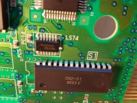
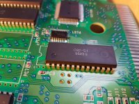
MVS Cart Graphics glitches (Kabuki Klash) - Reflow?

StalkS

New Challenger
Joined
Mar 7, 2011
Posts
51
Hey All, I was wondering if you could help me identify a problem I am having with an MVS cart.

The cart was was in pretty bad shape on the inside when I got the game. I knew this and hoped to breath some life back into it as the seller had managed to do so in the past. It actually had a dead beetle in it!

I've pretty much done everything I can think of to bring it back to life.

It has been cleaned thoroughly with Isopropanol and the contacts have been cleaned using a eraser and then actually polished with a mild brass cleaner and a Dremal to completely remove any oxidisation (You can see your face in them).

And I then went the extra mile and purchased a pretty awesome industrial ultrasonic cleaner and used de-ionised water to remove the dirt that was still collecting between the really fine chip pins.


As of now the boards look absolutely brand new but the original glitch is still there - A kind of inverted cross hatch. See Below.

20170227_095018 (Medium).jpg


The initial boot screen is also garbled and the Unibios menu is complete gibberish as well.

Looking at the glitch article on neogeodev.org they say:

"Glitches which:

Produce the same color pixel in 2x2 pixel blocks (dotted pattern)
Horizontally distort or misplace the sprites
Are caused by bad connections between video chips (LSPC/B1...), not between the console and the cart."


Do you think this matches my issue or should I be looking elsewhere?

I've invested so much time and effort into this I refuse to let it beat me!

Any help or advice would be greatly apprecitaed.

Cheers

StalkS
 
Last edited:

pulstar

Mickey's Coach
10 Year Member
Joined
Jun 6, 2011
Posts
585
Do you have any other carts to try on the motherboard? Do they have the same glitches? If not, it's definitely a cart issue.
 

pulstar

Mickey's Coach
10 Year Member
Joined
Jun 6, 2011
Posts
585
If other carts work fine and it is limited to this cart I would examine the board for any bad traces and check them with a multimeter to make sure they're all good, especially around the S Rom and the connections there. If that's all good, then, because it looks like a FIX layer problem, it would be pulling the S Rom, dumping it and comparing it with MAME.
 

StalkS

New Challenger
Joined
Mar 7, 2011
Posts
51
Thank pulstar I cannot see any broken traces but need to get my hands on a magnifying glass to be sure.

Cheers
 

pulstar

Mickey's Coach
10 Year Member
Joined
Jun 6, 2011
Posts
585
I would use a multimeter and set it to the continuity/beep function and make sure it's all good as well, especially on traces that look a little iffy but you can't confirm 100% by sight.
 

Xian Xi

JammaNationX,
15 Year Member
Joined
Dec 1, 2005
Posts
27,754
This is related to the S1 rom since it's only the fix layer. Sometimes on the MVS cart the traces near the two big holes get cut from the constant rubbing but those don't look like this, this might be more of broken solder joints or bad rom.
 

StalkS

New Challenger
Joined
Mar 7, 2011
Posts
51
This is related to the S1 rom since it's only the fix layer. Sometimes on the MVS cart the traces near the two big holes get cut from the constant rubbing but those don't look like this, this might be more of broken solder joints or bad rom.

Thanks Xian Xi & Pulstar - There are actually a couple of what look like "rubbing" marks on a couple of the traces near the big holes, but the traces do not look broken just exposed - I could be wrong of course. I won't be able to check until I can get my multimeter out of storage in the next day or two. If the trace is indeed broken is there an advised method of repair? I know you can purchase highly conductive paint, would that be best in these situations - I was thinking of trying to temporarily bridge it with some graphite from a pencil?

S1 Chip side
20170227_223755 (Medium).jpg

M1 Chip side
20170227_223813 (Medium).jpg

StalkS
 
Last edited:

pulstar

Mickey's Coach
10 Year Member
Joined
Jun 6, 2011
Posts
585
I use kynar wire to patch up traces, personally. Before trying to patch them I would test with a multimeter to confirm it cut. From sight it doesn't look like they are severed, just worn a little.
 

Xian Xi

JammaNationX,
15 Year Member
Joined
Dec 1, 2005
Posts
27,754
Can you snap a pic of all the solder joints on the S1 as well as the other side where the chip is? If all the joints are good and the chip doesn't have any rusting legs near the body, then I think the S1 might be going bad. You would have to remove it and verify it against a MAME dump.
 

StalkS

New Challenger
Joined
Mar 7, 2011
Posts
51
Hey Xian Xi,

Sure thing:

Rear
20170301_110655 (Medium).jpg

Top Right
20170301_110559 (Medium).jpg

Top Left
20170301_110550 (Medium).jpg

Cheers

StalkS
 

pulstar

Mickey's Coach
10 Year Member
Joined
Jun 6, 2011
Posts
585
That photo looks okay to me. The only suspect one looks like third in from left on the top row but still not too bad. Again, meter any of the suspect pins out and check connectivity. Next step if that checks out would be to pull it, dump it and check it against MAME.
 

Xian Xi

JammaNationX,
15 Year Member
Joined
Dec 1, 2005
Posts
27,754
Hmm, looks fine, I'd pull it and verify it as mentioned.
 

mikejmoffitt

Mickey's Coach
Joined
Feb 6, 2014
Posts
578
The screwy text on the bottom screams FIX layer tile addressing issue. You've got valid tiles, but some bit is stuck or missing causing it to choose ones from the wrong row/column.
 

StalkS

New Challenger
Joined
Mar 7, 2011
Posts
51
Thanks for all the advice guys - this resuscitation project is costing me an arm and a leg but I do enjoy the sense of achievement. Quick question I'm going to get my hands on a rework station - can you recommenda good entry level unit. Also not having dumped a chip before can you also recommend a good USB reader? Thanks
 

BIG BEAR

SHOCKbox Developer,
20 Year Member
Joined
Dec 14, 2001
Posts
8,353
Your S1 is dead.Burn a new one and replace it.
BB
 

StalkS

New Challenger
Joined
Mar 7, 2011
Posts
51
S1 replacement ordered from Fox. Thanks for the help throughout this gents.
 

StalkS

New Challenger
Joined
Mar 7, 2011
Posts
51
Just an update on this one. I finally got round to getting my soldering station out of storage and replaced the S1 chip that Fox kindly supplied. Unfortunately - still the exact same thing :(. Any suggestions or shall I just chalk this up to a dud buy?
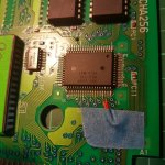
Cheers

StalkS
 

aha2940

AH, A, COLUMBIAN!,
Joined
Dec 15, 2013
Posts
2,529
Just an update on this one. I finally got round to getting my soldering station out of storage and replaced the S1 chip that Fox kindly supplied. Unfortunately - still the exact same thing :(. Any suggestions or shall I just chalk this up to a dud buy?

Cheers

StalkS

These carts are very repairable since they mostly contain ROM chips, that can be replaced with EPROMs and the board. If it's not a chip, it's a usually trace on the board, that simple. Just check very carefully for broken traces and you will fix it. If nothing of this work, one of the custom chips (PCM or NEO273) might be bad, but AFAIK that is not very common.
 

StalkS

New Challenger
Joined
Mar 7, 2011
Posts
51
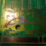
Gents, thanks you for the advice - I wasn't too sure what you meant by 'A1' so I traced the pins and made a bypass using kynar (Pictures below).

20170421_144011.jpg
20170421_144019.jpg

Still no joy!? Was that the right thing to do?

Cheers
 

Pedrobear

Cheng's Errand Boy
Joined
Mar 1, 2012
Posts
113
Your issue is A1 being always set to 1, check if there's a short between it and VCC along the trace. Adding a wire won't solve a short :D

another possibility would be a floating signal, make sure it is well connected.
 

Pedrobear

Cheng's Errand Boy
Joined
Mar 1, 2012
Posts
113
Err, scrap that i'm an idiot, tile # 2nd bit is A6, not A1. Somehow forgot some address lines are for the actual data :D

Check it it's shorted/floating

That's 273's pin 4, S1 pin 6.
 
Last edited:
Top