Mv-1f RGB to Scart *fixed*

amurphy245

Kuroko's Training Dummy
Joined
Apr 14, 2010
Posts
71
I’m currently consolizing my mv-1f ,I’m not using a video encoder as I just want RGB scart,I tapped into the video signals just behind the jamma pins (Except for sync which only seems to work on a separate point after looking at a jamma nation guide) and I’m also using a AES scart cable.

I’m getting a stable image but only the colour red ,I’ve checked all my work and tested for continuity and everything appears ok ,is there something I’m missing? Could it be the scart cable ? Do I need some resistors ?
 
Last edited:

DaisyAge

Galford's Armourer
Joined
Jun 10, 2018
Posts
457
Try moving the red wire in the scart head to either the blue or green pin and see if it changes colors. If it does you can rule out the resistors/scart cable. Next check the voltages on the JAMMA edge and report back with them. Also check the resistor bridge for burnt resistors. You can try and read their values but they really need to be pulled off to get an accurate reading.
 

amurphy245

Kuroko's Training Dummy
Joined
Apr 14, 2010
Posts
71
Try moving the red wire in the scart head to either the blue or green pin and see if it changes colors. If it does you can rule out the resistors/scart cable. Next check the voltages on the JAMMA edge and report back with them. Also check the resistor bridge for burnt resistors. You can try and read their values but they really need to be pulled off to get an accurate reading.

I should have probably mentioned that there are no video problems through my supergun set up it’s a perfect image ,Do you think the AES cable I bought may have the wrong resistor values? I will look into your other suggestions.
 

distropia

SouthTown StreetSweeper
10 Year Member
Joined
Apr 28, 2010
Posts
1,075
mvs to scart usually needs 220ohm or 330ohm on every colour line. If you have a tester, check that video output on every colour don't rise over 0.7 volts maximum.
 

amurphy245

Kuroko's Training Dummy
Joined
Apr 14, 2010
Posts
71
mvs to scart usually needs 220ohm or 330ohm on every colour line. If you have a tester, check that video output on every colour don't rise over 0.7 volts maximum.

I tried 220 ohm on all 3 lines and it didn’t work no picture this time ,obviously I’m doing something wrong here.

Does the sync line need a resistor ?
 

DaisyAge

Galford's Armourer
Joined
Jun 10, 2018
Posts
457
I should have probably mentioned that there are no video problems through my supergun set up it’s a perfect image ,Do you think the AES cable I bought may have the wrong resistor values? I will look into your other suggestions.

Can you link me to the cable you bought? I'm thinking you either got the wrong kind (like the genesis 1 cable) or they have incorrectly wired the cable with an incorrect schematic.
Can you also take a picture of the color lines and where you soldered them on the AES style connector you're using? You might have soldered the colors to the wrong pins and that would explain why the cable only picks up red.
Sync might need a resistor depending on the voltage coming from it and what monitor you're using "For your monitor not having a resistor would do nothing as most professional equipment can handle TTL (transistor-transistor logic) which is about 2 - 5Vp-p for a high signal. Consumer level equipment is made to handle 75 ohm terminated sync lines which I believe is 300mV - 1Vp-p.

Generally you can use a 470 ohm resistor (it can be different, like the SNES requiring a 330 ohm resistor) to bring TTL sync down to 75 ohm termination. "
 

amurphy245

Kuroko's Training Dummy
Joined
Apr 14, 2010
Posts
71
Here’s a link to the scart cable (I bought the mono one by accident) it’s well built but i can make any adjustments necessary to it https://www.retrocomputershack.com/RCS-Website/Products-Page/index.html

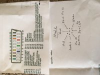
Here’s a picture I made of the din8 connector on the scart as if you were looking directly at it ,what I find interesting is he wired what I think should be ground to pin 19 on the scart connector ,it doesn’t appear to do anything with ground connected and doesn’t work as a sync either.

I need to go right back to basics with this as it’s driving me insane,firstly am I ok to solder to the points directly behind the main jamma slot ? I was initially following this guide http://www.jamma-nation-x.com/jammax/cmvs1fs.html but it’s a different board and he’s soldered to the resistors,however the sync line in that pic actually works even though it’s just red ,when I connect to the sync on the jamma connector it’s just a mess but I can’t understand why unless it needs a particular resistance value?

A9C1D21C-2831-4B5E-8768-6BD0AB0868A4.jpeg
 

DaisyAge

Galford's Armourer
Joined
Jun 10, 2018
Posts
457
Okay so that listing specifically says not for use with a consolized MVS which means that there's going to be some work to be done in the scart head itself.
Yes soldering behind the jamma edge should be fine, I've done this for most of the CMVS I make.
Your pinout is sus, try using the ones I've linked and put the 180 ohm resistor in the scart head if it's not there. The bottom pin (sync pin 19 in your diagram) should be ground.
On your AES connector on the MV1F you want to use the first image I linked. Ignore composite video and put sync on the pin above like in the photo.
Then check your scart head to make sure it matches the second photo.
https://www.bing.com/images/search?...AA17E2&selectedIndex=0&FORM=IRPRST&ajaxhist=0

https://www.bing.com/images/search?...A33076&selectedIndex=4&FORM=IRPRST&ajaxhist=0

This last image is so you can compare both the cable and connector pinouts at the same time. They have the pinout rotated 180 degrees so make sure you double check your work.
We can also get stereo to pass through this cable as long as the MV1F supports it, I can't remember off the top of my head. But first lets get the picture sorted!
 
Last edited:

amurphy245

Kuroko's Training Dummy
Joined
Apr 14, 2010
Posts
71
Ok I’ve done more investigating,the pin I previously marked at “pin 19” was wrong it does go to ground (pin 17)

The 5+ line is going to pin 16 is it really necessary to join it up to pin 8?

In the second picture you showed me you said ignore the composite pin going to pin 20 on the scart however my sync pin is wired up to pin 20 in the scart head so where do I put it ?
 

DaisyAge

Galford's Armourer
Joined
Jun 10, 2018
Posts
457
You can try getting it to work with only pin 16 but as far as I know yes the 5v is necessary on both pins to trigger the right switching mode on the TV. I am not experienced in SCART as I'm in America but if it doesn't work on only pin 16 then tie pins 16 and 8 with a 180ohm resistor and give the 5v to the resistor on the side that is connected to pin 8.
Sync goes to pin 20 on the scart head but it is supposed to go to pin 7 on the male AES cable. You need to make sure that the sync off the MVS is going to the same pin that the cable is expecting sync.
 

amurphy245

Kuroko's Training Dummy
Joined
Apr 14, 2010
Posts
71
I think the switching feature just makes your tv automatically pick up the signal or even turn the tv on but I’m no expert either ,I bridged those connections up with no change.

As it stands my scart and din connections are all correct.

I’ve done some more thinking and made some adjustments to my rgb points on the board i think I had the sync in the place of green because I followed that guide (even though it gave me a stable image) ,now I have 3 colours displaying on screen but the sync isn’t working right and I can’t understand why ,so at this point I believe I just have a sync issue.

I wish there was a guide for this board or even just an image of someone doing something similar.
 

amurphy245

Kuroko's Training Dummy
Joined
Apr 14, 2010
Posts
71
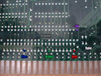
Can anyone explain this image (from jamma-nation)
Why did he tap into those points rather than the points directly behind the jamma slot ? My board is slightly different so can’t follow it but the sync line appears to work (gives me a stable image but missing colours) whereas the sync on the jamma slot doesn’t do anything,I’m puzzled.

8E22ADB5-1BC3-497A-BF96-06F493A20CB0.jpeg
 
Last edited:

DaisyAge

Galford's Armourer
Joined
Jun 10, 2018
Posts
457
So you can confirm you have all three colors showing up now? I'm guessing he chose those points because the are the last point before the edge and would make for a cleaner install.
What are you trying to use as a display? Some newer TV's and monitors don't like the native MVS timing because it isn't exactly standard.
 

amurphy245

Kuroko's Training Dummy
Joined
Apr 14, 2010
Posts
71
Yes i have all 3 colours but the sync on the jamma slot simply does nothing ,I’ve even connected/disconnected on the fly while it’s on and there is no difference to the image,I know that the Jamma pin is fine though because I previously used a supergun to my tv,I’m totally puzzled as to why it won’t sync.

I’m using a crt tv.
 

amurphy245

Kuroko's Training Dummy
Joined
Apr 14, 2010
Posts
71
Ok I fixed it ,wait till you hear this one.

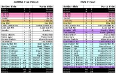
I had the jamma pinout wrong even after checking it many many times,what I didn’t realise was that pin 7 is still counted as a pin even though there’s no pin there just an empty space,Jesus Christ why do they do that?

Thanks for the help guys.

1AAA254D-3FF3-4F81-A572-D669CF5C9F63.jpeg
 
Top