CMVS AD725 Video Out

Joined
May 19, 2018
Posts
35
I am having some trouble with an RGB to s-video/comp converter for a CMVS based off of Ben Heck's decade old instructions. I thought I followed his schematic perfectly, but the colors were way off and the image was kind of jittery. So after doing a bit more research I found a post explaining that the RGB signals from the MVS signals should be sent through a voltage divider and then through an amp, so I attempted that before sending it into the AD725. I think it looks a little better, but the colors are still super over saturated and the image is still jittery in composite, although it is less noticeable in s-video. Does anyone know how to correct these issues?

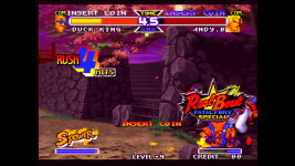
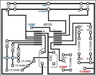
I've include the schematics here for Benhecks design, and the amp that I send the signals through before feeding them into it. I have also included direct feed capture of the s-video and composite so that you guys can see exactly what I'm talking about.
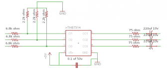
Screen Shot 2016-08-22 at 8.06.46 PM.png

rgb_circuit_engadget_howto.jpg

Composite Video

S-Video
 
Last edited:

Xian Xi

JammaNationX,
15 Year Member
Joined
Dec 1, 2005
Posts
27,750
Depending on the board, it could need a sync cleaner, it the colors are saturated then play with the value of the output caps but honestly, 220uf should be right. On your circuit, don’t run it through the THS, just go from the voltage divider directly to the AD725 circuit.
 
Joined
May 19, 2018
Posts
35
Depending on the board, it could need a sync cleaner, it the colors are saturated then play with the value of the output caps but honestly, 220uf should be right. On your circuit, don’t run it through the THS, just go from the voltage divider directly to the AD725 circuit.

OK I will try going straight from the voltage divider to the AD725 and then get back you. Should I use the THS amp for the RGB out though? I want this CMVS build to include Composite, S-Video, and RGB out. The board that I am using is an MV1ACHX, which I guess is just an MV1A from China. Is this one of the boards that requires a sync cleaner?
 

Xian Xi

JammaNationX,
15 Year Member
Joined
Dec 1, 2005
Posts
27,750
You can try splitting the signal at the AD725 input using only 124ohm resistors and the split going to the THS.
 
Joined
May 19, 2018
Posts
35
You can try splitting the signal at the AD725 input using only 124ohm resistors and the split going to the THS.

Hi sorry for the late reply, it's been a busy week. I tried coupling the output of the voltage divider using 220uf caps and then sending that directly into the AD725, but the image was way too dark. Also since you mentioned that certain boards may need a sync cleaner I purchased an lm1881. I tried to send the sync from the board through a 470 ohm resistor and a 220uf cap and then into the lm1881, then taking that output sync to the AD725. I was not able to get any picture from that, so I am assuming that I made a mistake and the lm1881 only works with composite video. I have yet to try swapping out the voltage divider with 124 ohm resistors, I will try it sometime this weekend and get back to you.
 
Joined
May 19, 2018
Posts
35
You can try splitting the signal at the AD725 input using only 124ohm resistors and the split going to the THS.

Ok so instead of using the amp i tried to feed the RGB lines through 124 ohm resistors then 220 caps before feeding it into the ad725 circuit as you recommended. The results look pretty much the same. What if I just try adding another resistor on pin 9 of the ad725 before the 220 uf cap, that should fix the over saturation at least in the s-video right?
 

Xian Xi

JammaNationX,
15 Year Member
Joined
Dec 1, 2005
Posts
27,750
Why are you adding caps on the input? The ones I’m talking about were for the output of the THS.
 
Joined
May 19, 2018
Posts
35
Why are you adding caps on the input? The ones I’m talking about were for the output of the THS.

My understanding was that inputs for the ad725 circuit needed to be coupled. I removed the ths for now, but I did not have caps on it's input before.
 

Xian Xi

JammaNationX,
15 Year Member
Joined
Dec 1, 2005
Posts
27,750
You need to reread my initial post, I think you are confusing yourself.
 
Joined
May 19, 2018
Posts
35
You need to reread my initial post, I think you are confusing yourself.

You are right, I confused myself. So you think the over saturation is caused by the caps on the output of the ad725 then? What range of values are acceptable to use?
 

Xian Xi

JammaNationX,
15 Year Member
Joined
Dec 1, 2005
Posts
27,750
Usually it ranges from 220, 330 or 470.

Try posting a pic because you might think it’s oversaturation but it could be something else. So you already tried RGB>124ohm>AD725 Circuit?
 
Joined
May 19, 2018
Posts
35
Usually it ranges from 220, 330 or 470.

Try posting a pic because you might think it’s oversaturation but it could be something else. So you already tried RGB>124ohm>AD725 Circuit?

I have not tried RGB>124ohm>AD725 Circuit, but as mentioned I tried RGB>124ohm>220uf>AD725 Circuit. I can try it without the caps next if you think it will help. I have to order some more caps in order to mess with the output. I will also try posting pictures when I get a chance. My thought was that it is saturation because when I lower the saturation setting on my framemeister to way bellow the default value, from 32 to 19, it looks OK. I don't think that the color is the fault of the framemeister because if I hook it up to my other, no name, general s-video/composite to hdmi upscaler the colors are still way off. That being said the jittering on the composite output remains. I'm certain that it is not the neo-geo board it's self, as I have tried RGB>124ohm>220uf>scart connector on my framemeister and it looked great.
 
Joined
May 19, 2018
Posts
35
Usually it ranges from 220, 330 or 470.

Try posting a pic because you might think it’s oversaturation but it could be something else. So you already tried RGB>124ohm>AD725 Circuit?

OK so I tried swapping out the 220uf caps on the luma and chroma from the ad725 with some 330uf caps. I don't really see much of a difference. It still appears oversaturated, most notably on the reds. Peoples skin looks orange. I have some 470uf caps that I can also try, but I'm not sure if it will affect much. Here are some pics. I also uploaded a test capture clip to youtube in case there are some details not showing in these pics.

https://youtu.be/LQhKQEjWwqY

vlcsnap-2019-04-28-15h03m04s949.png
vlcsnap-2019-04-28-15h03m28s549.png
vlcsnap-2019-04-28-15h03m41s651.png
vlcsnap-2019-04-28-15h03m59s950.png
vlcsnap-2019-04-28-15h04m06s615.png
vlcsnap-2019-04-28-15h04m16s292.png
vlcsnap-2019-04-28-15h04m29s233.png
vlcsnap-2019-04-28-15h04m34s395.png
vlcsnap-2019-04-28-15h04m46s856.png

https://youtu.be/LQhKQEjWwqY
 

Xian Xi

JammaNationX,
15 Year Member
Joined
Dec 1, 2005
Posts
27,750
It doesn’t look oversaturated to me but seems like your TV/monitor has the contrast too high.
 

Neo Alec

Ned's Ninja Academy Dropout
20 Year Member
Joined
Dec 7, 2000
Posts
11,994
Use 220uf caps.I finally just installed pots in my MV-1C and compared against my NGCD to figure out the correct resistor values. 330 ohms turned out to be correct.
 
Last edited:
Joined
May 19, 2018
Posts
35
It doesn’t look oversaturated to me but seems like your TV/monitor has the contrast too high.

Yes but the colors don't look that way on the rgb, and the composite output is still jittery.

Use 220uf caps.I finally just installed pots in my MV-1C and compared against my NGCD to figure out the correct resistor values. 330 ohms turned out to be correct.

On the inputs or the outputs?
 
Joined
May 19, 2018
Posts
35
It doesn’t look oversaturated to me but seems like your TV/monitor has the contrast too high.

Sorry for double posting here. Looking at it on a different monitor it doesn't look as over-saturated as I remember. But the composite output is still a problem because it is super jittery, almost like watching a vhs tape, could it be a sync issue. Would implementing the luma trap help with this?
 
Last edited:
Top