Hi guys, this is my first post here in this forum.
I´ve read a lot over the internet during the past weeks trying to solve my problems, and decided to ask for more help. I´ve already posted a thread on NLG forum but got no answers.
I live in Portugal, and I´ve found a pair of arcade cabinets at good price with several damage to the monitors and game PCBs due to rodent and bird dejections sitting on the boards for the past 20 years… I´ve fixed both monitors, and sold one cabinet.
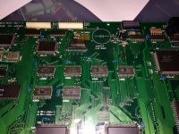
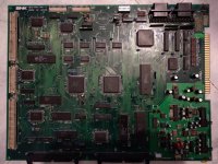
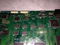
Now I have a working jamma cabinet, and two SNK MV1-1 Boards both with serious damage due to battery leak and animal cohabitation.
They are the MV1-1 version with a LSPC-A0, PRO-CO, NEO-ZMC2, NEO FO, PRO-BO, NEO-GO, NEO-EO, NEO-DO, NEO-IO, etc…
Exactly this version: https://www.mvs-scans.com/index.php/MV1-1
At the time of purchase, I tested the boards as they were on the cabinet, and nothing worked well. (If I knew what was inside the cabinets, I would never turned them on. I know it was a big mistake.)
Now, I decided to clean everything and test the boards again to diagnose and try to repair them, if possible. They are both crazy as expected from the visible damage of the battery leakage and animal activity… But I really want to fix these boards and also want to learn a lot more about these amazing systems, so I started working on them.
I have some experience regarding electronics repairs and finding faulty simple components, so I already tested the monitor for good and the power supply is working fine and clean. I have a pandora´s box for testing arcade machines and it works flawlessly on this cabinet, but I dont like it. The ideal solution would be to repair the two boards, and sell one. If not possible, repair one to fit in the cabinet and save another for spare parts.
But here is what I´ve already done to the boards:
Replace all 470uF16v. caps, because they were measuring 250uF capacitance.
Replace all 100uF caps, because they were measuring 25uF capacitance.
Removed batteries and 470ohm resistors. Cleaned all battery leak damage with IPA. Let boards dry in the sun.
Fixed all visible bad traces (dozens), and continuity tested everything found broken on the two boards.
Continuity tested the following list:
MV1-1 (my version of two continuity lists combined, that I´ve found in another thread, and shows continuity in these MV1-1 boards) I adapted some pins that I´ve found a bit different on this version, so if you have any official continuity list for this version of the board, please let me know.
SP1 BIOS (LSPC-A0 version of the board)
1----5V
2----GND
3----68000-12 (54), LSPC (23), NEO B0 (60), NEO G0 (50), 43256 (19) D2
4----68000-12 (55), LSPC (22), NEO B0 (59), NEO G0 (49), 43256 (18) D2
5----68000-12 (56), LSPC (18), NEO B0 (58), NEO G0 (48), 43256 (17) D2
6----68000-12 (57), LSPC (17), NEO B0 (57), NEO G0 (47), 43256 (16) D2
7----68000-12 (58), LSPC (16), NEO B0 (56), NEO G0 (34), 43256 (15) D2
8----68000-12 (59), LSPC (15), NEO B0 (55), NEO G0 (33), 43256 (13) D2
9----68000-12 (60), LSPC (14), NEO B0 (54), NEO G0 (32), 43256 (12) D2
10---68000-12 (61), LSPC (13), NEO B0 (53), NEO G0 (31), 43256 (11) D2
11---GND
12---68000-12 (62), LSPC (12), NEO G0 (18), 43256 (19) Backup RAM
13---68000-12 (63), LSPC (11), NEO G0 (17), 43256 (18) Backup RAM
14---68000-12 (64), LSPC (10), NEO D0 (3), 43256 (17) Backup RAM
15---68000-12 (01), LSPC (9), NEO D0 (2), 43256 (16) Backup RAM
16---68000-12 (02), LSPC (8), NEO D0 (1), 43256 (15) Backup RAM
17---68000-12 (03), LSPC (7), NEO D0 (64), 43256 (13) Backup RAM
18---68000-12 (04), LSPC (6), NEO D0 (63), 43256 (12) Backup RAM
19---68000-12 (05), LSPC (5), NEO D0 (62), 43256 (11) Backup RAM
20---NEO-GO (59)
21---68000-12 (29), PRO C0 (60), NEO E0 (64), 43256 (10) C2 D2, HC259 (1)
22---68000-12 (30), PRO C0 (61), NEO E0 (1), 43256 (09) C2 D2, HC259 (2)
23---68000-12 (31), PRO C0 (62), NEO E0 (2), 43256 (08) C2 D2, HC259 (3)
24---68000-12 (32), PRO C0 (63), NEO E0 (3), 43256 (07) C2 D2, HC259 (13)
25---68000-12 (33), NEO B0 (92), NEO E0 (4), 43256 (06) C2 D2
26---68000-12 (34), NEO B0 (93), NEO E0 (15), 43256 (05) C2 D2
27---68000-12 (35), NEO B0 (94), NEO E0 (16), 43256 (04) C2 D2
28---68000-12 (36), NEO B0 (95), NEO E0 (17), 43256 (03) C2 D2
29---68000-12 (37), NEO B0 (96), NEO E0 (18), 43256 (25) C2 D2
30---GND
31---68000-12 (38), NEO B0 (97), NEO E0 (19), 43256 (24)
32---68000-12 (39), NEO B0 (98), NEO E0 (20), 43256 (21)
33---68000-12 (40), NEO B0 (99), NEO E0 (21), 43256 (23)
34---68000-12 (41), NEO E0 (31), 43256 (2) C2 D2, LS05 (01) (R9)
35---68000-12 (42), NEO E0 (32), 43256 (26) C2 D2, LS05 (03) (R9)
36---68000-12 (43), NEO E0 (33), 43256 (1) C2 D2, LS05 (05) (R9)
37---68000-12 (44), NEO E0 (34), LS05 (11) (Q9)
38---5V
39---5V
40---5V
Only the “LS05” don’t give continuity on both boards, but if I follow the traces, visually I can’t find any physical connection.
Now I dont know what else to do, because everything I tested is OK, and I don´t find any more broken traces. I have a small DIY oscilloscope (DSO138) but I dont know what to look for in the TTL comunication, and I dont know if I can use it to test logic circuits. It supports a maximum freq of 200KHz. Can I use this if I don’t have a logic probe?
So, the behavior of the boards is like this at the moment:
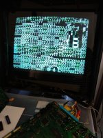
Board 1 (worst damage): Does lots of green garbage on the screen, flickers and clicks like the watchdog symptom, but if I let it on for a while (2or3 min) sometimes it stops reseting and shows fixed green trashy squares on the screen. Same happens if I remove the bios Chip. Bios chip makes no difference in this problem.
If I pass my finger gently on the top of some RAM chips it influences the garbage on the screen. Nothing is getting minimally hot, except for the YM2610, and lower 5814...
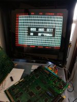
Board 2: Boots to weird text like:
IIEE AA RROO
DDRRSS IIEERRAADD
00000022 5555 5500
Sometimes, if i let it on for a while, it starts to show white garbage on the screen… If I pass my finger gently on the top of ZMC2 IC it influences the garbage on the screen. If I tap in it with something plastic it has no effect.
Some chips get a little warm but the warmest is the YM2610.
All this tested with no game, or socket board inserted. I have a world heroes 2 cartridge that I tested on a four slot MVH and it works fine!
I tried flexing the board, or pressing on the chips, but nothing changed. IF I leave the board on the sun, and power it on right away, the garbage on the screen changes a bit.
I really want to fix this boards, first of all because I can´t stand the idea of trashing this awesome systems. I´m a console collector, I love gaming systems, and I love to fix stuff and want to learn as much as I can about electronics, specially repairing old classic games machines to keep them running. Home consoles and arcades. Bringing these old things back to life gives me a lot of joy… and headache :P
I´ve read a lot of amazing repair logs from "channelmaniac", but I didn´t find any matching these symptoms...
Is there any fan made schematics on these systems that shows what continuity should be between all pins of all chips? I can’t find schematics for this model, so if I can help build one too, I´m available to contribute!
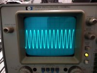
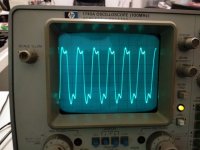
Is there any signal I can measure with my DIY oscilloscope or multimeter to track down the problem?
I have some videos and images of the problems:
Board 1: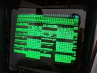 https://www.youtube.com/watch?v=pmfjtrPJqmY
Board 2: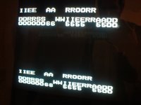
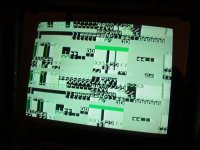
Sorry for so many questions!
Thanks for any help, and I´m sorry if my English is not perfect.
Best regards!
T.S.
I´ve read a lot over the internet during the past weeks trying to solve my problems, and decided to ask for more help. I´ve already posted a thread on NLG forum but got no answers.
I live in Portugal, and I´ve found a pair of arcade cabinets at good price with several damage to the monitors and game PCBs due to rodent and bird dejections sitting on the boards for the past 20 years… I´ve fixed both monitors, and sold one cabinet.
Now I have a working jamma cabinet, and two SNK MV1-1 Boards both with serious damage due to battery leak and animal cohabitation.
They are the MV1-1 version with a LSPC-A0, PRO-CO, NEO-ZMC2, NEO FO, PRO-BO, NEO-GO, NEO-EO, NEO-DO, NEO-IO, etc…
Exactly this version: https://www.mvs-scans.com/index.php/MV1-1
At the time of purchase, I tested the boards as they were on the cabinet, and nothing worked well. (If I knew what was inside the cabinets, I would never turned them on. I know it was a big mistake.)
Now, I decided to clean everything and test the boards again to diagnose and try to repair them, if possible. They are both crazy as expected from the visible damage of the battery leakage and animal activity… But I really want to fix these boards and also want to learn a lot more about these amazing systems, so I started working on them.
I have some experience regarding electronics repairs and finding faulty simple components, so I already tested the monitor for good and the power supply is working fine and clean. I have a pandora´s box for testing arcade machines and it works flawlessly on this cabinet, but I dont like it. The ideal solution would be to repair the two boards, and sell one. If not possible, repair one to fit in the cabinet and save another for spare parts.
But here is what I´ve already done to the boards:
Replace all 470uF16v. caps, because they were measuring 250uF capacitance.
Replace all 100uF caps, because they were measuring 25uF capacitance.
Removed batteries and 470ohm resistors. Cleaned all battery leak damage with IPA. Let boards dry in the sun.
Fixed all visible bad traces (dozens), and continuity tested everything found broken on the two boards.
Continuity tested the following list:
MV1-1 (my version of two continuity lists combined, that I´ve found in another thread, and shows continuity in these MV1-1 boards) I adapted some pins that I´ve found a bit different on this version, so if you have any official continuity list for this version of the board, please let me know.
SP1 BIOS (LSPC-A0 version of the board)
1----5V
2----GND
3----68000-12 (54), LSPC (23), NEO B0 (60), NEO G0 (50), 43256 (19) D2
4----68000-12 (55), LSPC (22), NEO B0 (59), NEO G0 (49), 43256 (18) D2
5----68000-12 (56), LSPC (18), NEO B0 (58), NEO G0 (48), 43256 (17) D2
6----68000-12 (57), LSPC (17), NEO B0 (57), NEO G0 (47), 43256 (16) D2
7----68000-12 (58), LSPC (16), NEO B0 (56), NEO G0 (34), 43256 (15) D2
8----68000-12 (59), LSPC (15), NEO B0 (55), NEO G0 (33), 43256 (13) D2
9----68000-12 (60), LSPC (14), NEO B0 (54), NEO G0 (32), 43256 (12) D2
10---68000-12 (61), LSPC (13), NEO B0 (53), NEO G0 (31), 43256 (11) D2
11---GND
12---68000-12 (62), LSPC (12), NEO G0 (18), 43256 (19) Backup RAM
13---68000-12 (63), LSPC (11), NEO G0 (17), 43256 (18) Backup RAM
14---68000-12 (64), LSPC (10), NEO D0 (3), 43256 (17) Backup RAM
15---68000-12 (01), LSPC (9), NEO D0 (2), 43256 (16) Backup RAM
16---68000-12 (02), LSPC (8), NEO D0 (1), 43256 (15) Backup RAM
17---68000-12 (03), LSPC (7), NEO D0 (64), 43256 (13) Backup RAM
18---68000-12 (04), LSPC (6), NEO D0 (63), 43256 (12) Backup RAM
19---68000-12 (05), LSPC (5), NEO D0 (62), 43256 (11) Backup RAM
20---NEO-GO (59)
21---68000-12 (29), PRO C0 (60), NEO E0 (64), 43256 (10) C2 D2, HC259 (1)
22---68000-12 (30), PRO C0 (61), NEO E0 (1), 43256 (09) C2 D2, HC259 (2)
23---68000-12 (31), PRO C0 (62), NEO E0 (2), 43256 (08) C2 D2, HC259 (3)
24---68000-12 (32), PRO C0 (63), NEO E0 (3), 43256 (07) C2 D2, HC259 (13)
25---68000-12 (33), NEO B0 (92), NEO E0 (4), 43256 (06) C2 D2
26---68000-12 (34), NEO B0 (93), NEO E0 (15), 43256 (05) C2 D2
27---68000-12 (35), NEO B0 (94), NEO E0 (16), 43256 (04) C2 D2
28---68000-12 (36), NEO B0 (95), NEO E0 (17), 43256 (03) C2 D2
29---68000-12 (37), NEO B0 (96), NEO E0 (18), 43256 (25) C2 D2
30---GND
31---68000-12 (38), NEO B0 (97), NEO E0 (19), 43256 (24)
32---68000-12 (39), NEO B0 (98), NEO E0 (20), 43256 (21)
33---68000-12 (40), NEO B0 (99), NEO E0 (21), 43256 (23)
34---68000-12 (41), NEO E0 (31), 43256 (2) C2 D2, LS05 (01) (R9)
35---68000-12 (42), NEO E0 (32), 43256 (26) C2 D2, LS05 (03) (R9)
36---68000-12 (43), NEO E0 (33), 43256 (1) C2 D2, LS05 (05) (R9)
37---68000-12 (44), NEO E0 (34), LS05 (11) (Q9)
38---5V
39---5V
40---5V
Only the “LS05” don’t give continuity on both boards, but if I follow the traces, visually I can’t find any physical connection.
Now I dont know what else to do, because everything I tested is OK, and I don´t find any more broken traces. I have a small DIY oscilloscope (DSO138) but I dont know what to look for in the TTL comunication, and I dont know if I can use it to test logic circuits. It supports a maximum freq of 200KHz. Can I use this if I don’t have a logic probe?
So, the behavior of the boards is like this at the moment:
Board 1 (worst damage): Does lots of green garbage on the screen, flickers and clicks like the watchdog symptom, but if I let it on for a while (2or3 min) sometimes it stops reseting and shows fixed green trashy squares on the screen. Same happens if I remove the bios Chip. Bios chip makes no difference in this problem.
If I pass my finger gently on the top of some RAM chips it influences the garbage on the screen. Nothing is getting minimally hot, except for the YM2610, and lower 5814...
Board 2: Boots to weird text like:
IIEE AA RROO
DDRRSS IIEERRAADD
00000022 5555 5500
Sometimes, if i let it on for a while, it starts to show white garbage on the screen… If I pass my finger gently on the top of ZMC2 IC it influences the garbage on the screen. If I tap in it with something plastic it has no effect.
Some chips get a little warm but the warmest is the YM2610.
All this tested with no game, or socket board inserted. I have a world heroes 2 cartridge that I tested on a four slot MVH and it works fine!
I tried flexing the board, or pressing on the chips, but nothing changed. IF I leave the board on the sun, and power it on right away, the garbage on the screen changes a bit.
I really want to fix this boards, first of all because I can´t stand the idea of trashing this awesome systems. I´m a console collector, I love gaming systems, and I love to fix stuff and want to learn as much as I can about electronics, specially repairing old classic games machines to keep them running. Home consoles and arcades. Bringing these old things back to life gives me a lot of joy… and headache :P
I´ve read a lot of amazing repair logs from "channelmaniac", but I didn´t find any matching these symptoms...
Is there any fan made schematics on these systems that shows what continuity should be between all pins of all chips? I can’t find schematics for this model, so if I can help build one too, I´m available to contribute!
Is there any signal I can measure with my DIY oscilloscope or multimeter to track down the problem?
I have some videos and images of the problems:
Board 1:
 https://www.youtube.com/watch?v=pmfjtrPJqmY
Board 2:


Sorry for so many questions!
Thanks for any help, and I´m sorry if my English is not perfect.
Best regards!
T.S.

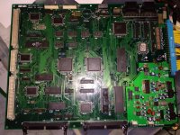
 ]:
]: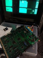
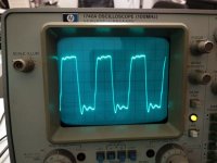

 Spent some money on spare ram chips, but it was worth it!

