Consolized - MV1A RGB

Joined
Jan 28, 2019
Posts
7
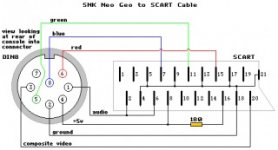
Hi I am researching how to consolize my MV1A, I am bit confused over RGB options, Can I just wire a din socket to the RGB outputs on the board and then connect this to the TV with a din to scart connector or do I need some sort of encoder in between the board connections and the din. Also do I need to add resistors to the ends of the RGB wires before I wire to the socket if so what type also where do I connect the sync. I have been looking at the diagram attached but there is no sync.


Any help would be appreciated.

Thanks

Brendan1495
 

Attachments

  • Din.jpg
    Din.jpg
    21.3 KB · Views: 60
Last edited:
Joined
Jan 28, 2019
Posts
7
Thanks for the quick reply, so I need an encoder between the RGB lines from the board and the output socket?
 

daskrabs

Ace Ghost Pilot
10 Year Member
Joined
Aug 23, 2010
Posts
1,314
Not an encoder as such, but at least resistors, per the link.
 

adeneo

n00b
Joined
Apr 17, 2018
Posts
40
Sorry to be a pain, I am new all this, what size resistors would you use?

Thanks

There's like three paragraphs under "video encoder", read them?


JNX said:
Please note that some LCD TVs may need different resistor values as for some the picture looks perfect on a CRT but on an LCD looked washed out. Standard values for an LCD TV use would be around 150ohm 1/4 watt on each RGB line. On CRTs you might not even need resistors but 80ohm should be fine
 
Joined
Nov 24, 2018
Posts
8
Hi Brendan,

I've just finished consolizing a MV1A and I'm in the UK too. Mine is hooked up to a Panasonic CRT with RGB scart input and seems to be working fine.

I started with 75ohm resistors on R,G & B, but increased that to 120ohm since the picture was too bright.

You'll also need a resistor on sync (labelled composite video). The range I saw was 330-470ohm. I used 470.

Rather than hooking it up to a DIN socket, why not just wire directly to a scart socket (female)? Then you can just use a standard male to male SCART lead to hook up to your TV.

Bear in mind if you do that, that some of the pins get swapped by the male to male cable. There's a good wiring diagram for a supergun with SCART socket on this page:
http://8bitplus.co.uk/projects/jamma-supergun/

That's basically what I used for sync, RGB and audio.

EDIT - I should add that you get left and right audio from the mv1a after doing the 5v and stereo out mods listed on the jamma-nation-x page above - not direct from the jamma edge.

Robin
 
Last edited:

Xian Xi

JammaNationX,
15 Year Member
Joined
Dec 1, 2005
Posts
27,750
You can use resistors or build an RGB Buffer using a THS7314. I usually put all the resistors and such in the machine so the cable is just wire only.
 
Joined
Jan 28, 2019
Posts
7
Hi Brendan,

I've just finished consolizing a MV1A and I'm in the UK too. Mine is hooked up to a Panasonic CRT with RGB scart input and seems to be working fine.

I started with 75ohm resistors on R,G & B, but increased that to 120ohm since the picture was too bright.

You'll also need a resistor on sync (labelled composite video). The range I saw was 330-470ohm. I used 470.

Rather than hooking it up to a DIN socket, why not just wire directly to a scart socket (female)? Then you can just use a standard male to male SCART lead to hook up to your TV.

Bear in mind if you do that, that some of the pins get swapped by the male to male cable. There's a good wiring diagram for a supergun with SCART socket on this page:
http://8bitplus.co.uk/projects/jamma-supergun/

That's basically what I used for sync, RGB and audio.

EDIT - I should add that you get left and right audio from the mv1a after doing the 5v and stereo out mods listed on the jamma-nation-x page above - not direct from the jamma edge.

Robin

Thanks a lot for all your help will give it a go at weekend, think I have a bit more of an idea now
 
Top