Neo Geo Consolized MVS1FS Power Supply/Video Interference

superfry63

Kuroko's Training Dummy
Joined
May 13, 2018
Posts
76
On my MVS1FS I get some weird video noise. (MVS->JROK->RGB->OSSC)

It's basically like a bunch of waves that scroll from top to bottom and you can notice it easily on solid black.

On another tv I have, there are like "white sparkles/waves" that flare up from the bottom of the screen.

I had been using a PWR+ 5V 3A power supply which I rigged up to the jamma pins. It Measures 4.92V at the jamma pins.

Recently I picked up one of the following as per James/JNX in a thread I found:

https://www.ebay.ca/itm/AC-Converte...K:MEBIDX:IT&_trksid=p2060353.m2749.l2649#rwid

Oddly enough - the interference is like x3 times worse with this new PSU - but on the bright side I'm assuming it's all coming down the the PSU causing the issues. It comes in at 5.20V at the jamma pins.

Is there anything I can do to the PSU's to help clean them up? Maybe add in some sort of filter, or should I just stop right now and get a different PSU with the ability to adjust the 5V? (and if so which one would you recommend for a consolized MVS1FS)
 

Neo Alec

Ned's Ninja Academy Dropout
20 Year Member
Joined
Dec 7, 2000
Posts
11,990
What's the Jrok in there for? Sharing the RGB signal with an encoder can cause issues.
 

superfry63

Kuroko's Training Dummy
Joined
May 13, 2018
Posts
76
At the time I was following the JNX tutorial and used the Jrok instead of the Neobitz as it had pots on the RGB lines and the 220uf caps in case the colors where all funky. Also it had the other outputs if I took the system to a friends house and they didn't have an OSSC or etc.
 

Neo Alec

Ned's Ninja Academy Dropout
20 Year Member
Joined
Dec 7, 2000
Posts
11,990
I would remove it from the equation just to see if it helps.
 

superfry63

Kuroko's Training Dummy
Joined
May 13, 2018
Posts
76
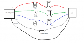
Just got it all apart now. So instead of using the JROK the following diagram should be okay if I pull right off the board? (except this will be to a din socket)
neo geo paint.png

Well that and the signal goes into the center pin and then output and ground on the outer pins?

Also, does Video Ground vs Ground on the jamma matter?
 
Last edited:

Neo Alec

Ned's Ninja Academy Dropout
20 Year Member
Joined
Dec 7, 2000
Posts
11,990
That will work. You should also put a cap on the sync line. Any ground will work.
 

superfry63

Kuroko's Training Dummy
Joined
May 13, 2018
Posts
76
Thanks, I think that is actually a drawing you drew up on another thread lol.

Mind if I ask what PSU and MVS you have?
 

Neo Alec

Ned's Ninja Academy Dropout
20 Year Member
Joined
Dec 7, 2000
Posts
11,990
I stole the image from another forum.

I'm using an MV-1C with an official Japanese AES 5v power supply. It's nice to have but not ideal. I'm kind of looking for a quality 5v aftermarket alternative.
 

superfry63

Kuroko's Training Dummy
Joined
May 13, 2018
Posts
76
Thanks,

I'm just waiting to get some caps and pots in to bypass the JROK but I was thinking about getting a decent Arcade Power Supply with adjustable 5V and testing that out.

What I can't figure out is if I should try to find a linear one or a switching. It sounds like Switching could introduce some noise. Anyone have any experience with this one:

https://na.suzohapp.com/products/power_supplies/80-0064-00
 

Hawwa

B. Jenet's Firstmate
Joined
Sep 21, 2018
Posts
408
It may have nothing to do with this thread but... What are the caps in the rgb lines for?

I have an MV1C which I connect directly to scart rgb (with 1k pots on each color line so I can adjust the intensity, they're around 250ohms each). Nothing on the sync line and no caps as mentioned... Should I change anything from my setup? I think it works properly but I bet there's always room for improvement.
 

Neo Alec

Ned's Ninja Academy Dropout
20 Year Member
Joined
Dec 7, 2000
Posts
11,990
They smooth out the signals on the lines. Proper circuit design mandates their presence. But if you're having no issues with your setup you may not need them.
 

GadgetUK

Ace Ghost Pilot
Joined
Sep 27, 2013
Posts
1,323
It may have nothing to do with this thread but... What are the caps in the rgb lines for?

Blocking DC. Without them you can end up with a DC offset and additional current gets drawn. Best to ensure you have caps inbetween.
 

Xian Xi

JammaNationX,
15 Year Member
Joined
Dec 1, 2005
Posts
27,750
BTW the JROK has RGB Passthrough, interference will usually come from a shitty power supply or a recap is needed on the PCB. Remember that some of these boards are almost 30 years old. Also make sure your ground wire is big enough.
 

superfry63

Kuroko's Training Dummy
Joined
May 13, 2018
Posts
76
What size would you recommend for the ground wire? I know the one included with the encoder from the MVS to the JROK is tiny.

The board has been recapped and I'm just waiting on a suzo happ power supply with adjustable 5V - (x2 PSU's i'm using now are not great)

Still waiting on some parts to just completely bypass the JROK to rule that out.
 

Xian Xi

JammaNationX,
15 Year Member
Joined
Dec 1, 2005
Posts
27,750
What size would you recommend for the ground wire? I know the one included with the encoder from the MVS to the JROK is tiny.

The board has been recapped and I'm just waiting on a suzo happ power supply with adjustable 5V - (x2 PSU's i'm using now are not great)

Still waiting on some parts to just completely bypass the JROK to rule that out.

For power entry I use 18awg, for signal wires I usually use 24-22awg but ground connections are usually 22awg.
 

Hawwa

B. Jenet's Firstmate
Joined
Sep 21, 2018
Posts
408
They smooth out the signals on the lines. Proper circuit design mandates their presence. But if you're having no issues with your setup you may not need them.

Blocking DC. Without them you can end up with a DC offset and additional current gets drawn. Best to ensure you have caps inbetween.

OK... I don't see any problem image related... How does the DC offset affect image? Any way I can notice if I should be putting the Caps?

BTW, the ressistor on the sync line... what is it for?
 

Neo Alec

Ned's Ninja Academy Dropout
20 Year Member
Joined
Dec 7, 2000
Posts
11,990
The resistor brings the signal strength down to the correct level for consumer equipment. Otherwise the picture will be too bright.
 

Hawwa

B. Jenet's Firstmate
Joined
Sep 21, 2018
Posts
408
The resistor brings the signal strength down to the correct level for consumer equipment. Otherwise the picture will be too bright.

That much I know about the pots in the rgb lines but the ressistor on the sync line? Does also affect brightness?
 

Neo Alec

Ned's Ninja Academy Dropout
20 Year Member
Joined
Dec 7, 2000
Posts
11,990
Oh, sorry, you asked about the sync line. The sync on the board is TTL level. Far too strong for TV's and upscalers. It's the same reason Genesis/MD RGB cables need a resistor built in to make it safe. It will most likely work without the resistor but you my be damaging your equipment in the long run.
 

Hawwa

B. Jenet's Firstmate
Joined
Sep 21, 2018
Posts
408
Oh, sorry, you asked about the sync line. The sync on the board is TTL level. Far too strong for TV's and upscalers. It's the same reason Genesis/MD RGB cables need a resistor built in to make it safe. It will most likely work without the resistor but you my be damaging your equipment in the long run.

Well, didn't know about that. Thanks for the info, I'll put the ressistor on the sync line then. Does it have to be exactly 470? I ask because if the value may vary somehow I'd put a pot instead of a fixed ressitor.

The cap on the sync line is also of 220uF?

Thanks man.

BTW, I see there are caps for differente voltages (16V, 25V, 35V...) which one should I use?
 
Last edited:

Xian Xi

JammaNationX,
15 Year Member
Joined
Dec 1, 2005
Posts
27,750
BTW, I see there are caps for differente voltages (16V, 25V, 35V...) which one should I use?

Rule of thumb is double the expected voltage. Sync is usually 5v so at least 10v.
 

Xian Xi

JammaNationX,
15 Year Member
Joined
Dec 1, 2005
Posts
27,750
Thanks for the reply. Does the same apply for the caps on the r b g lines?

Yes, any caps. RGB you can probably get away with 6.3v ones but 10v is usually the lowest I go.
 

Hawwa

B. Jenet's Firstmate
Joined
Sep 21, 2018
Posts
408
Yes, any caps. RGB you can probably get away with 6.3v ones but 10v is usually the lowest I go.

Wonderful. As always thanks a ton. I've got me some 16V (lowest they had) so I'll just put those.
 
Top