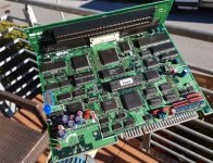
Check continuity between LSPC2-A2 pin 23 and both RAM5 & RAM6 pins 10.
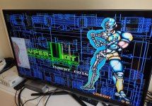
If the self-tests pass, that should be good.
More plausible: check between LSPC2-A2 pin 112 and cart slot CHA A3 (bottom connector, top row of pins, third pin from the left).
If the self-tests pass, that should be good.
More plausible: check between LSPC2-A2 pin 112 and cart slot CHA A3 (bottom connector, top row of pins, third pin from the left).
") Let me know if it could be linked from the wiki.
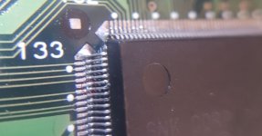
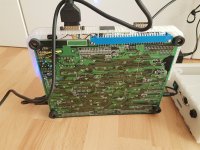
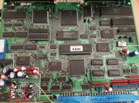
Let me know if it could be linked from the wiki. Even though the board is in good condition and my loupe check didn't show any bad traces