- Joined
- Oct 3, 2005
- Posts
- 6,059
After playing around a bit with my Analog Blackfin JAMMA board, I decided I wanted to try a more classic hardware design. I set out to make a working JAMMA PCB using nothing but standard 5v through-hole parts, using a well-known CPU that already had free tools.
Quickly, I realized that it would require a ton of parts to build anything approximating a sprite engine. With an 8-bit CPU, I didn't want to deal with a framebuffer, either. So I decided my project would be limited in scope, to a machine with just a tilemap for video.
This generally meant that I'd be building a puzzle game, as anything else would likely require some form of pixel-writing. So I decided to make a Tetris clone.
I like the Z80, and it's still made in speed grades up to 20MHz, so I started with that. I decided to use 32KBytes of RAM and 32KBytes of ROM, because those parts (62256 and 27256) are commonly available as well. That made the memory address space easy.
The video system is nearly as simple as possible. A set of dual-port RAMs (so the timing is easier) contains a tilemap, 2 bytes per 8x8 tile. 13 bits from each tilemap word address a pattern, and 3 bits address a palette. The patterns are stored in 4 64KByte ROMs, which are attached to 4 74LS166 shift registers to read out 8x 4bpp pixels. The 3 bits from the tilemap, and 4 bits from the pattern pixel, are used to address a palette ROM, containing a color palette. The color palette output goes to a set of 3x 4-bit DACs, made from resistor arrays. So it's basically one big chain of look-up tables in ROMs.
I initially thought that I'd use a bunch of individual 8-bit output ports to control the video system. With a single interrupt at 15KHz, I should be able to re-load a starting tile address at each line, straight from the CPU. It would work something like the Atari 2600 in that respect. I decided that was too much overhead, though. It was simpler to get a microcontroller for that stuff. So the video system is controlled by an 8051-compatible microcontroller, running at 500KHz machine cycles. It's essentially a big busy-loop that toggles vsync/vblank pulses at the right time. It controls a port to set which video line is scanned out, and can reset a pair of 74LS193 counters to count tiles within the line.
For other peripherals, I eventually settled on an 8255. It takes up the whole IO address space. I use port A to output commands to a microcontroller that makes sounds, and port B to output some extra address bits to the ROM containing the video color palettes. Port C, being bit-addressable, controls a set of shift registers an an I2C bus.
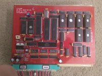
I spent a while working out each part of this design, drawing up a schematic in Eagle. I laid out a circuit board and ordered it from DirtyPCBs.
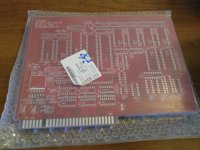
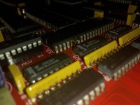
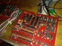
I put the board together, enough to get it booting and theoretically put something on screen. I had to wire up an adapter for the program ROM, because I wanted to use a battery-backed SRAM package instead of a UV EPROM.
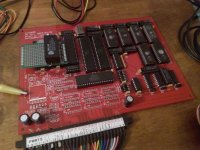
Having waited 10 days for the order, I had whipped up an emulator on my computer. I could run my Z80 code on the emulator to see what it would look like. So when I put it together - and sorted out a devious issue with a transposed address line on the ROM - I got it up and running with the same test code.
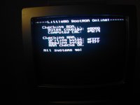
Unfortunately, the 8255 didn't seem to work. I could read the ports as inputs just fine, but nothing I wrote to it seemed to do anything. Much debugging followed. I have an HP 1662CS logic analyzer which helped with logging tons of signals.
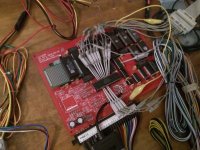
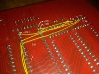
Eventually I re-read the datasheet and found out that the 8255 treats the ~CS pin like an address pin, not a strobe. Deasserting ~CS won't properly terminate a write, and I had just wired the ~CS, ~RD, and ~WR straight to the Z80's ~IORQ, ~RD, and ~RW. So I effectively wasn't holding the ~CS pin long enough. I re-did the decoding to just tie that pin low, and decode ~IORQ and ~RD/~WR into strobes specifically for the 8255, using a 74LS38.
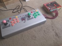
For the sake of testing, I attached a Super Nintendo controller cable instead of the shift-registers on board. Normally, there would be a set of 3x 8-bit shift registers to latch 24 switch inputs from the JAMMA edge. A Super Nintendo controller is basically the same thing in a nice small package, though. Aside from inverting some of the signals in software, and getting them in a different order, it hooks right up.
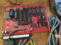
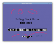
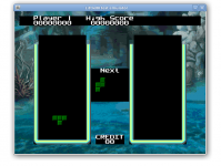
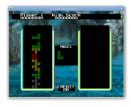
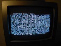
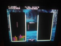
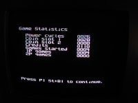
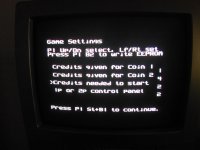
I've gotten the software to the point where I can run through a bunch of test-mode screens, and at least start to display the game graphics. There are some utilities on my computer for converting PNG files into tile-mapped backgrounds for the hardware.
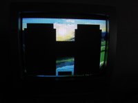
I'm writing up the basics of the actual game loop now. I hope to post some more progress when it's ready.
Quickly, I realized that it would require a ton of parts to build anything approximating a sprite engine. With an 8-bit CPU, I didn't want to deal with a framebuffer, either. So I decided my project would be limited in scope, to a machine with just a tilemap for video.
This generally meant that I'd be building a puzzle game, as anything else would likely require some form of pixel-writing. So I decided to make a Tetris clone.
I like the Z80, and it's still made in speed grades up to 20MHz, so I started with that. I decided to use 32KBytes of RAM and 32KBytes of ROM, because those parts (62256 and 27256) are commonly available as well. That made the memory address space easy.
The video system is nearly as simple as possible. A set of dual-port RAMs (so the timing is easier) contains a tilemap, 2 bytes per 8x8 tile. 13 bits from each tilemap word address a pattern, and 3 bits address a palette. The patterns are stored in 4 64KByte ROMs, which are attached to 4 74LS166 shift registers to read out 8x 4bpp pixels. The 3 bits from the tilemap, and 4 bits from the pattern pixel, are used to address a palette ROM, containing a color palette. The color palette output goes to a set of 3x 4-bit DACs, made from resistor arrays. So it's basically one big chain of look-up tables in ROMs.
I initially thought that I'd use a bunch of individual 8-bit output ports to control the video system. With a single interrupt at 15KHz, I should be able to re-load a starting tile address at each line, straight from the CPU. It would work something like the Atari 2600 in that respect. I decided that was too much overhead, though. It was simpler to get a microcontroller for that stuff. So the video system is controlled by an 8051-compatible microcontroller, running at 500KHz machine cycles. It's essentially a big busy-loop that toggles vsync/vblank pulses at the right time. It controls a port to set which video line is scanned out, and can reset a pair of 74LS193 counters to count tiles within the line.
For other peripherals, I eventually settled on an 8255. It takes up the whole IO address space. I use port A to output commands to a microcontroller that makes sounds, and port B to output some extra address bits to the ROM containing the video color palettes. Port C, being bit-addressable, controls a set of shift registers an an I2C bus.
I spent a while working out each part of this design, drawing up a schematic in Eagle. I laid out a circuit board and ordered it from DirtyPCBs.

I put the board together, enough to get it booting and theoretically put something on screen. I had to wire up an adapter for the program ROM, because I wanted to use a battery-backed SRAM package instead of a UV EPROM.

Having waited 10 days for the order, I had whipped up an emulator on my computer. I could run my Z80 code on the emulator to see what it would look like. So when I put it together - and sorted out a devious issue with a transposed address line on the ROM - I got it up and running with the same test code.

Unfortunately, the 8255 didn't seem to work. I could read the ports as inputs just fine, but nothing I wrote to it seemed to do anything. Much debugging followed. I have an HP 1662CS logic analyzer which helped with logging tons of signals.

Eventually I re-read the datasheet and found out that the 8255 treats the ~CS pin like an address pin, not a strobe. Deasserting ~CS won't properly terminate a write, and I had just wired the ~CS, ~RD, and ~WR straight to the Z80's ~IORQ, ~RD, and ~RW. So I effectively wasn't holding the ~CS pin long enough. I re-did the decoding to just tie that pin low, and decode ~IORQ and ~RD/~WR into strobes specifically for the 8255, using a 74LS38.
For the sake of testing, I attached a Super Nintendo controller cable instead of the shift-registers on board. Normally, there would be a set of 3x 8-bit shift registers to latch 24 switch inputs from the JAMMA edge. A Super Nintendo controller is basically the same thing in a nice small package, though. Aside from inverting some of the signals in software, and getting them in a different order, it hooks right up.

I've gotten the software to the point where I can run through a bunch of test-mode screens, and at least start to display the game graphics. There are some utilities on my computer for converting PNG files into tile-mapped backgrounds for the hardware.

I'm writing up the basics of the actual game loop now. I hope to post some more progress when it's ready.


 When I build the other copies (I've got 10 bare PCBs) the extra chip will probably sit on top of the 8255. And yeah, I have a couple other designs I want to try. One thing at a time, though.