Boot Issues on MV-1C

thrasherx

n00b
Joined
Mar 30, 2018
Posts
6
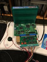
In the process of installing a uni-bios on my MV-1C, I lifted a pad. I wasn't able to fully boot the uni-bios and reverted back to the stock bios. Now, without a cart in the slot, I sometimes can boot to the system debug menu, but othertimes I get stuck with a scrambled screen instead of the green boot screen. When this happens, the system hangs and I don't get to the debug menu.

IMG_8806-compressed.jpg

I just received a 138-in-1 and have had no luck getting it to boot, even when I've been able to get to the debug bios.

IMG_8805-compressed.jpg

I haven't been able to trace it down to a specific chip, or wire, but have tried wiggling wires on boot to find the culprit.

Any advice before I give up and buy another MV-1C?
 

Attachments

  • IMG_8805-compressed.jpg
    IMG_8805-compressed.jpg
    1.5 MB · Views: 70
  • IMG_8806-compressed.jpg
    IMG_8806-compressed.jpg
    1.5 MB · Views: 69

Xian Xi

JammaNationX,
15 Year Member
Joined
Dec 1, 2005
Posts
27,750
That's bios related, most likely the pad you broke off, the fix you made isn't exactly as permanent as it needs to be.
 

thrasherx

n00b
Joined
Mar 30, 2018
Posts
6
That's bios related, most likely the pad you broke off, the fix you made isn't exactly as permanent as it needs to be.

Thanks! I wonder what a more permanent fix looks like. I traced it out to one of the chips near the cartridge slot and get continuity the whole way. I’ll have to put it under a scope and take a closer look. I wouldn’t mind using the neobiosmasta but can’t find any info on where to get the qfp socket for it.
 

thrasherx

n00b
Joined
Mar 30, 2018
Posts
6
A quick update: I repaired the pulled trace using a component leg, ensuring it’s not shorted to ground or to any adjacent legs. I got the same garbled video. Sometimes I would get the crosshatch screen. Next, I cleaned the cartridge and cartridge slot. Also, I used a Dc Power supply to power the system, thinking maybe it was a power draw issue. Now I consistently get the crosshatch screen, which is good. The 138-in-1 cart now displays a solid green or solid white screen. It’s drawing .8 amps at 5V.
 

thrasherx

n00b
Joined
Mar 30, 2018
Posts
6
Another update: I got the 138-in-1 working by bypassing the external PCB and using jumpers to select the game. I’m not sure what’s wrong with it but I’ll take it up with the AliExpress seller. Thanks!
 

Xian Xi

JammaNationX,
15 Year Member
Joined
Dec 1, 2005
Posts
27,750
Judging by the pics of the multiboard, it looks like it needs 12v to power a few things on board.
 

thrasherx

n00b
Joined
Mar 30, 2018
Posts
6
Thank you! I came to the same conclusion tonight after looking at the 12V relays and test point. I got the daughter board working! Unfortunately, it doesn’t play nice with my OSSC and TV. I have to use either pass through or 3X mode for the menu to display and no setting seems to work when the game eventually loads. I get a 272p / 15.72 kHz / 57 Hz signal at the menu and a 264p / 15.62 kHz / 59.19 Hz once the game loads.

I’m debating doing an Arduino / Shift register solution to switch between the games, but a breadboard will do for now to switch games until I figure out a final dip replacement solution. It’s interesting that I don’t have any video issues when the board is bypassed. The signal is 264p / 15.62 kHz / 59.18 Hz which is nearly identical to the output of the game when I load through the multiboard menu.
 
Last edited:
Top