NoAffinity
Kuroko's Training Dummy

- Joined
- Mar 20, 2017
- Posts
- 74
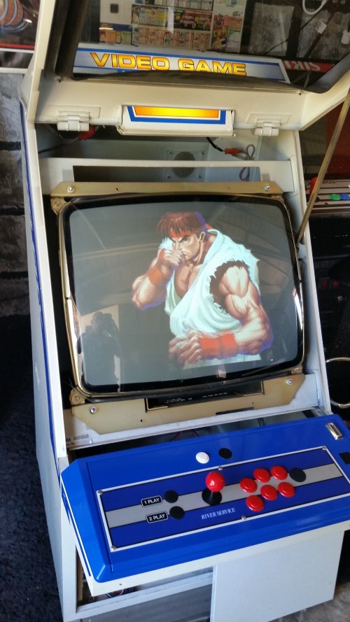
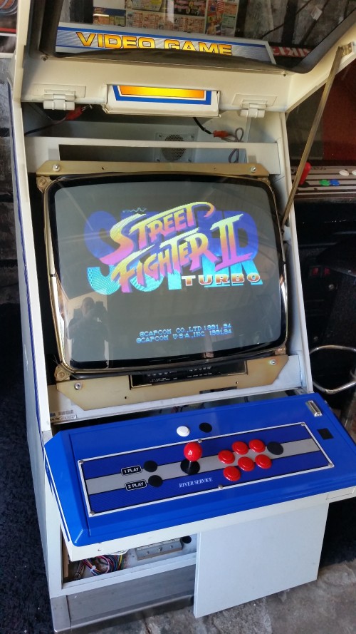
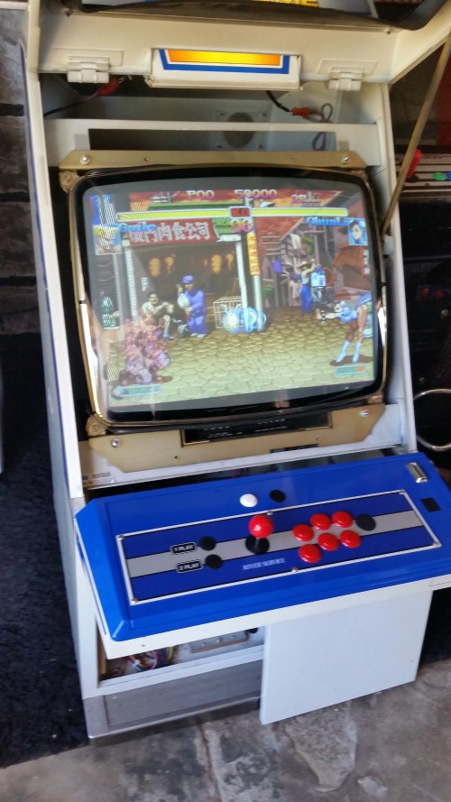
I've posted this across a couple forums, not getting much help, mucking through it with what little information I can find on this monitor. Hoping someone here is familiar with it (standard Aero City 26" monitor, but NOT the same as the more common MS8-26SU).
I did a cap kit on the chassis. Was working before, is not working now. I have rechecked all my work about 10 times now...verified orientation, correct placement, even pulled all the old caps from the trash and re-checked what was installed against what came out.
AC power is good where it lands at the board. Fuses are good. There's a very faint hum or buzz coming from the neck area...the standard sound of a monitor in operation, but much much more faint. No neck glow.
Following this thread for guidance, from someone who had the same experience on 3 of 4 capped chassis: https://forums.arcade-museum.com/sho...d.php?t=295290
I am powering the monitor with an iso tap, plugged in on the isolated side, getting around 102-103V AC through fuse F901. I've read these chassis are okay at 120V, and I was clearly running it on 120V for the few months I've had it so far, with no problems. But, nonetheless, I'm going with what's marked on the tube sticker for testing.
Soldered a wire to the negative side of the filter cap for my ground. Getting 93.8V DC at F902. I put the isotap up one tick, to get around 108V AC, and still 93.8V DC at F902.
Checked voltage at the IC301 vertical board and there was nothing there...at least not on pin 9, which is supposed to be VCC. I started desoldering, and unbeknownst to me, was doing it with the monitor still plugged in. :-o I got to I think the 4th or 5th pin, sucked up the solder, and instantaneously the monitor came on. Scared the crap out of me.
I immediately unplugged and discharged, and got that beatiful POP from the discharge. I then resoldered and checked for shorts, figuring I must've had a short, and found 2 pins shorted, which are continuous via the vertical board, and 2 pins shorted that are continuous on the chassis. No other shorts that shouldn't be there. Re-powered and nothing.
Then I looked closer, and the connection at the board that goes to pin 9 is floating. It is a through hole with no connectivity. And there's no way I'm installing the vertical board backwards. It will not physically fit if rotated 180 degrees. I also looked at a picture I had taken before starting work, and it is properly oriented.
Also checked Q901 - 94.1VDC on the base, 93.9VDC on the emitter.
I adjust B+ voltage up to get a solid 100V DC at F901.
I then realized pin 9 is labeled on the board, and it seems the pins get numbered counter-clockwise, with 1 being at the top right of the notched end of the chip. Pin 9 was measuring around 10.7V DC.
Checked voltage across the filter cap - 133.8V
No improvement other than that single instance when I was desoldering with the board powered.
I'm starting to dissect IC301 and ins/outs to/from it.
Any other suggestions?
I did a cap kit on the chassis. Was working before, is not working now. I have rechecked all my work about 10 times now...verified orientation, correct placement, even pulled all the old caps from the trash and re-checked what was installed against what came out.
AC power is good where it lands at the board. Fuses are good. There's a very faint hum or buzz coming from the neck area...the standard sound of a monitor in operation, but much much more faint. No neck glow.
Following this thread for guidance, from someone who had the same experience on 3 of 4 capped chassis: https://forums.arcade-museum.com/sho...d.php?t=295290
I am powering the monitor with an iso tap, plugged in on the isolated side, getting around 102-103V AC through fuse F901. I've read these chassis are okay at 120V, and I was clearly running it on 120V for the few months I've had it so far, with no problems. But, nonetheless, I'm going with what's marked on the tube sticker for testing.
Soldered a wire to the negative side of the filter cap for my ground. Getting 93.8V DC at F902. I put the isotap up one tick, to get around 108V AC, and still 93.8V DC at F902.
Checked voltage at the IC301 vertical board and there was nothing there...at least not on pin 9, which is supposed to be VCC. I started desoldering, and unbeknownst to me, was doing it with the monitor still plugged in. :-o I got to I think the 4th or 5th pin, sucked up the solder, and instantaneously the monitor came on. Scared the crap out of me.
I immediately unplugged and discharged, and got that beatiful POP from the discharge. I then resoldered and checked for shorts, figuring I must've had a short, and found 2 pins shorted, which are continuous via the vertical board, and 2 pins shorted that are continuous on the chassis. No other shorts that shouldn't be there. Re-powered and nothing.
Then I looked closer, and the connection at the board that goes to pin 9 is floating. It is a through hole with no connectivity. And there's no way I'm installing the vertical board backwards. It will not physically fit if rotated 180 degrees. I also looked at a picture I had taken before starting work, and it is properly oriented.
Also checked Q901 - 94.1VDC on the base, 93.9VDC on the emitter.
I adjust B+ voltage up to get a solid 100V DC at F901.
I then realized pin 9 is labeled on the board, and it seems the pins get numbered counter-clockwise, with 1 being at the top right of the notched end of the chip.
Pin 9 was measuring around 10.7V DC.Checked voltage across the filter cap - 133.8V
No improvement other than that single instance when I was desoldering with the board powered.
I'm starting to dissect IC301 and ins/outs to/from it.
Any other suggestions?
Last edited:
 <- me
<- me