TV MVS RGB input hack stalled on account of darkness

Berq

n00b
Joined
Aug 31, 2016
Posts
6
So I recently acquired one of my arcade grails: a Neo Geo 4-slot. Got it on the cheap because it was using a Zenith TV + RGB>composite converter board instead of a proper monitor. After becoming immediately dissatisfied with the blur and artifacts this introduced, and having no money to buy a 25" arcade monitor, I reasoned the TV HAD to use an RGB signal at SOME point. And though I didn't even know what a "chassis" was, I had a mission. That led me to the discovery that people had figured out the OSD hack about a decade ago. Bonus.

Without further backstory, I got it working.
Essentially. Partly. Everything's too dark.
I set my camera to full-manual mode and took some pictures. The two "RGB" images aren't zoomed, I just had my camera on a different tripod, closer to the screen. Either way, the difference in brightness between the two sets of pictures accurately represents the problem.

My gut says the solution goes beyond simple tweaks to resistor or capacitor values, and will involve additional circuitry/components, but I'm out of my depth.

8gmdTQ.gif


I don't want to flood this first post with information, so I'll supply it as needed.
 

aha2940

AH, A, COLUMBIAN!,
Joined
Dec 15, 2013
Posts
2,528
Or maybe you need to amplify the RGB signals? don't know, just a thought.
 

Berq

n00b
Joined
Aug 31, 2016
Posts
6
As it turns out, that got the brightness up where it needed to be. Now I just have to figure out why that introduced some color banding. Too busy at work this week. I'll elaborate more later.
 

Berq

n00b
Joined
Aug 31, 2016
Posts
6
OK, just finished a time-intensive project at work, so I've been able to work a bunch more on connecting my MVS to the TV.

I've tried two different amplifiers, both with compromised success. First, while waiting for the THS7314 amp I ordered to arrive, I modified my RGB>Composite converter board...
mIAzjca.png

I tapped the unused pins of the MB3516A chip that drive 75Ω RGB video signals, and got video that had the right brightness and contrast:
WW61uJt.png

BUT...
DerT9Ww.png

...suffered from this terrible horizontal color bleed. Unacceptable. I'm fairly confident this is due to the poorly engineered 75Ω drivers on the chip, and not botched soldering. Lifting the pins for the encoded video (chroma, Y, Y-trap, and composite video) didn't change anything.

Once my THS7314 arrived, I connected it without any additional resistors, and got overly bright, super-high contrast colors. After loads of trial and error, the best (and simplest) circuit I can figure out looks like this:
8VpKIo9.png

(with the addition of a 0.1μF polarized cap across the +5V and ground pins of the amplifier, not shown). The bottom half of the diagram is the TV chassis. I'm inserting the RGB signal directly after the OSD chip (disabled, also not shown).
This configuration gives me a picture that looks like so:
wl9HrkI.png
8iJJDKd.png
vZj1jUE.png

The color bands that plagued the other amplifier are gone, but the brightness is no better than WITHOUT the amp!

I have the motivation to continue, but I'm plain out of ideas on what to try next.
 
Last edited:

Berq

n00b
Joined
Aug 31, 2016
Posts
6
That creates more questions than answers, as he never says if he used a THS7314 or not, is feeding the signal to a totally different location, and is working with a totally different video source.

Interesting reading for a future project, perhaps.
 

mikejmoffitt

Mickey's Coach
Joined
Feb 6, 2014
Posts
578
With the gain down through the divider / amplifier removed, you might do well just turning up the bias for each color (DC offset), or even the flyback's "screen" control.
 

Berq

n00b
Joined
Aug 31, 2016
Posts
6
or even the flyback's "screen" control.
If only it were as simple as the flyback adjustment. I occasionally tweak it a little, eternally hopeful, but it never brings out colors that weren't visible before.

That said, I could be overlooking something obvious. When I started this project, I didn't even know what a chassis was. I knew that arcade boards worked with RGB video signals, and TVs (at SOME point) must work with separate RGB signals, so I reasoned this TV modification MUST be possible, even if not practical, and that someone else HAD to have already tried it. Even now, I'm grossly incompetent to pull this off on my own. What I have going for me is that I'm passionate about the Neo Geo, too poor to buy a proper arcade monitor, reasonably bright, and cavalier enough to risk breaking something. But my biggest asset is the wealth of information shared by people, such as yourself, who have already succeeded. I've been a student of your blog and various forum posts since early October, and am far more knowledgeable about CRTs and video signals than before. So thank you.
you might do well just turning up the bias for each color (DC offset)
And now it's time to go get learned up on how to adjust bias!
 
Last edited:

Heinz

Parteizeit
15 Year Member
Joined
Feb 13, 2005
Posts
22,333
Considering the RGB signal from an MVS board is quite high for a TV set there must be some resistance somewhere. Typically it would be exceedingly bright.
 

Berq

n00b
Joined
Aug 31, 2016
Posts
6
OK. So I broke down and bought an old oscilloscope, because I'm the kind of guy that'll buy a $150 tool he doesn't know how to use instead of spending $200 to just buy the monitor he needs.

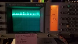
Anyway, here's what the TV's OSD signal looks like at the green pin of the video processor. It reads between 2-3 VDC. I assume this is the model of a proper signal for this chassis, more or less:
20170424_073453.jpg

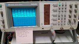
Next, for reference, here's what the signal looks like of the Metal Slug title screen when the MVS's video cable is unconnected, measured between green and ground:
20170426_055607.jpg
(Yeah, I should've taken ALL the pictures with the lights on, but I wanted the settings window to show up well.)

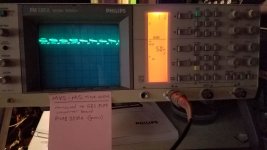
Now here's the M.S. title screen again (exact same frame, thanks to the pause switch), passed through the MB3516A (RGB out), sent to the chassis, and measured at the same pin. Signal is right around 2 V. On the TV, the image is the correct brightness, but has the aforementioned horizontal color bleeding, so this junky encoder chip isn't a viable solution to the problem.
20170424_080228.jpg

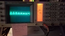
And finally, this is the signal when the MVS video is connected directly to the chassis with 75 Ohm termination (M.S. title screen, green channel). This is the configuration that gives an image that's too dark:
20170424_075306.jpg

I'm barely beyond the level of oscilloscope novice, but the results didn't really surprise me, as much as I'm able to understand what I'm looking at. Seems proper signals are delivered over a narrower, but higher, voltage range than my dark signal. My problem now: I have no idea what to do with this information. Do I need to somehow "reshape" the signal while also increasing its voltage?
 
Last edited:
Top