I picked up a (fairly) cheap Sony BVM-2015S that was made in 1992. While I'm sure it has a lot of hours on it, it looks like the picture tube has been replaced at least once, which it seems Sony used to do every 30,000 hours of operation way-back-when. The picture quality is pretty good, and I'd like to keep this thing alive.
After turning it on and smelling electrolyte, I opened up the unit and found a series of five mid-size capacitors that had leaked fluid all over what I believe is the main power distribution PCB.
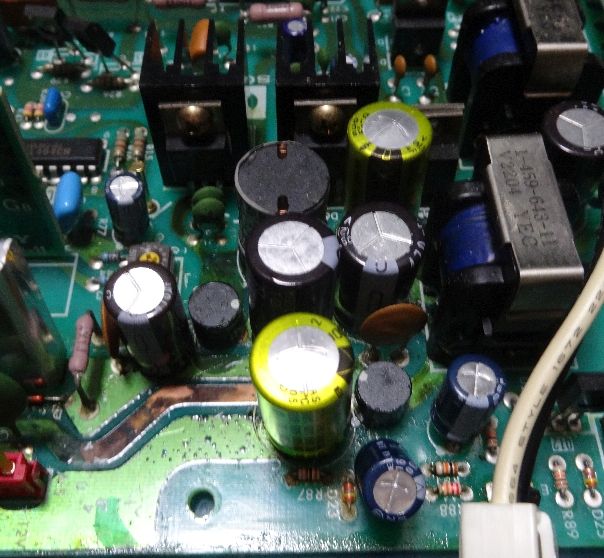
It's the two yellow ones, the two in between, and the similar-sized one on the left. By the time I took this photo, I had already cleaned off much of the fluid from the board.
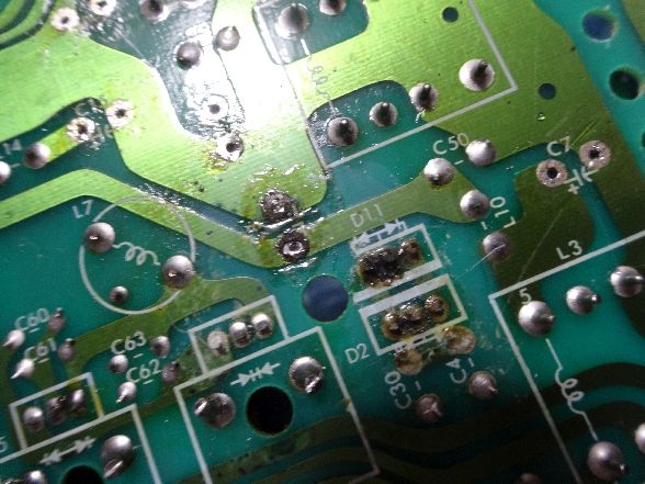
Eventually, I was able to remove the caps, and it looked like this:
A lot of the green coating is peeling away, but at least the copper traces are still intact.
What are not doing so well are the solder pads. I suspect that the very first cap to go was the top-yellow one, and the solder pads under it appear to be dissolved away.
A lot of the pads that were under the other caps are in poor condition as well. Not to mention, the resistor and the diode at the bottom of the picture don't look so hot, either.
Then there's the black thing in the top left corner. This is actually two components back-to-back, and I think they are transistors. One way or another, they seemed to suffer the worst corrosion, and on the bottom of the board, you can see this. Look at the two groups of three pins:
Even at 500 degrees Celsius, my soldering iron couldn't get this to melt again. Flux, alcohol, vinegar and baking soda don't seem to do much to it. I'm assuming that the pins are either shorted, or they're out of circuit entirely.
-------------------
So, what should I do about all of this?
Tell me if my idea sounds stupid.
This board goes inside of a big metal case, and there is a lot of room to spare. For an amateur like me, an easy-sounding solution is to put all the new caps and replacement components on a small board like this. Then, I could run wires from the leads of these components to the next solder pad on the corresponding trace where the old components were on the main PCB.
Is this dumb? Is there a reason why it wouldn't work electronically?
-----------------------
A few other questions:
1. When I replace the caps, is ripple-current important? The caps have voltage, temperature and uF ratings on them, but not ripple current, and that sounds like an important factor in capacitors. Do you have any other advice about selecting new caps?
2. Bizarrely, the leaky caps still give good uF ratings with a multimeter. Their resistance is a little screwy, but aside from buying an ESR meter, is there anything I can do to diagnose bad caps?
3. If my daughter-card idea isn't dumb, what kind of wire should I use?
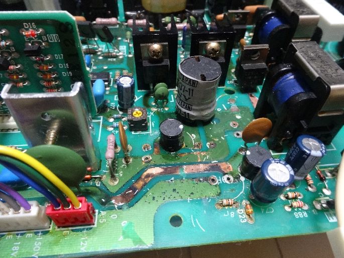
4. Does anyone know what those small black things are in the first and second photo? I mean the things with the white dots on top. They just say SONY with some number that doesn't turn up anything on Google. They don't seem corroded.
5. Assuming that those are transistors, what should I be careful about when replacing them?
---------------
Thank you!
After turning it on and smelling electrolyte, I opened up the unit and found a series of five mid-size capacitors that had leaked fluid all over what I believe is the main power distribution PCB.
It's the two yellow ones, the two in between, and the similar-sized one on the left. By the time I took this photo, I had already cleaned off much of the fluid from the board.
Eventually, I was able to remove the caps, and it looked like this:
A lot of the green coating is peeling away, but at least the copper traces are still intact.
What are not doing so well are the solder pads. I suspect that the very first cap to go was the top-yellow one, and the solder pads under it appear to be dissolved away.
A lot of the pads that were under the other caps are in poor condition as well. Not to mention, the resistor and the diode at the bottom of the picture don't look so hot, either.
Then there's the black thing in the top left corner. This is actually two components back-to-back, and I think they are transistors. One way or another, they seemed to suffer the worst corrosion, and on the bottom of the board, you can see this. Look at the two groups of three pins:
Even at 500 degrees Celsius, my soldering iron couldn't get this to melt again. Flux, alcohol, vinegar and baking soda don't seem to do much to it. I'm assuming that the pins are either shorted, or they're out of circuit entirely.
-------------------
So, what should I do about all of this?
Tell me if my idea sounds stupid.
This board goes inside of a big metal case, and there is a lot of room to spare. For an amateur like me, an easy-sounding solution is to put all the new caps and replacement components on a small board like this. Then, I could run wires from the leads of these components to the next solder pad on the corresponding trace where the old components were on the main PCB.
Is this dumb? Is there a reason why it wouldn't work electronically?
-----------------------
A few other questions:
1. When I replace the caps, is ripple-current important? The caps have voltage, temperature and uF ratings on them, but not ripple current, and that sounds like an important factor in capacitors. Do you have any other advice about selecting new caps?
2. Bizarrely, the leaky caps still give good uF ratings with a multimeter. Their resistance is a little screwy, but aside from buying an ESR meter, is there anything I can do to diagnose bad caps?
3. If my daughter-card idea isn't dumb, what kind of wire should I use?
4. Does anyone know what those small black things are in the first and second photo? I mean the things with the white dots on top. They just say SONY with some number that doesn't turn up anything on Google. They don't seem corroded.
5. Assuming that those are transistors, what should I be careful about when replacing them?
---------------
Thank you!
Last edited:
")