CMVS video bright and washed out

Jamie

NEST Puppet
Joined
May 24, 2002
Posts
167
I hope someone can help me me with an issue i'm having with a CMVS i recently bought. The board type is an MV-1C.

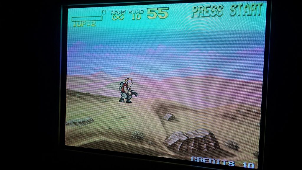
The video output on it is really bright and washed out, making it unplayable. The guy who i bought it off says that it was ok on his B&O TV, but it has the issue on everything i've tried it on, Sony Trinitron CRT, Pioneer Plasma and XRGB Mini. I am using RGB over a scart cable.

Here is a shot of the problem, it's actually worse in person, i think the camera has taken some of the brightness out of it.

20160217_222908_resized_zpse99jqh6r.jpg


Having done some reading, i think that the answer is to install some resistors to the RGB lines to counter the video output of the board, however i can't find any info on what exactly needs doing. I want to try and fix the issue myself if possible, but have limited experience with soldering and electrical work.

I would really appreciate some advice on what i actually need to use and what work requires doing on the board.
 

Yodd

Iori's Flame
20 Year Member
Joined
Feb 7, 2002
Posts
8,214
Easy fix would be to add somewhere between 120ohm to 150ohm resistors in line with each of the RGB signals.

So if you have a scart cable, open up the scart hood and install a resistor inline with the Red, green and blue signal. One resistor for each color.

I think the usual recommended value is 124ohm.
 

Jamie

NEST Puppet
Joined
May 24, 2002
Posts
167
Thanks for the tip, sounds fairly straight forward. Thought i would need to solder directly onto the mobo, which i was nervous about, so modding a cheap cable makes things a little easier.
 

GohanX

Horrible Goose
20 Year Member
Joined
Sep 28, 2001
Posts
12,511
1/4 watt resistors are fine, those would work but 3w resistors are physically huge.
 
Last edited:

Xian Xi

JammaNationX,
15 Year Member
Joined
Dec 1, 2005
Posts
27,750
What CMVS is this? I'm assuming it's the AI as their RGB dim fix was wrong and this would be the product of that.
 

Jamie

NEST Puppet
Joined
May 24, 2002
Posts
167
Hi, no it's not the AI, it's one i bought from someone on another forum that they'd built themselves. Sounds like the same issue though.
 

mikejmoffitt

Mickey's Coach
Joined
Feb 6, 2014
Posts
578
I suspect something else is wrong. See how the hills have bright pink in their shadowing? One of the red output bits might be stuck floating or high from NEO-GRZ. Hopefully this is just camera funny-business and I'm wrong, and it'll just be fixed with resistors for dimming.
 

mourix

n00b
Joined
Feb 22, 2016
Posts
28
Considering the black and white parts of the image are still fine I'd say it's just the TV struggling with the high input level.

If you google "jamma to scart" there are quite some tutorials and schematics to help you getting the right resistors in there. Usually it's 150-220 ohms on the RGB and sync lines.
 

shadowkn55

Genbu's Turtle Keeper
15 Year Member
Joined
Dec 9, 2006
Posts
2,386
Are the rgb lines connected directly to the jamma edge?
 

Xian Xi

JammaNationX,
15 Year Member
Joined
Dec 1, 2005
Posts
27,750
I suspect something else is wrong. See how the hills have bright pink in their shadowing? One of the red output bits might be stuck floating or high from NEO-GRZ. Hopefully this is just camera funny-business and I'm wrong, and it'll just be fixed with resistors for dimming.

That is a possibility. I had a board that did that and it was a few floating pins on the GRZ.
 

Jamie

NEST Puppet
Joined
May 24, 2002
Posts
167
Are the rgb lines connected directly to the jamma edge?

Yeah, i think they are. I should be able to test if the resistors on the RGB lines works or not soon, have got a custom RGB cable coming in the post. Hopefully it'll sort this out, thanks for everyones help so far.
 

mikejmoffitt

Mickey's Coach
Joined
Feb 6, 2014
Posts
578
Actually, the best thing to do would be to go into test mode and look at the color bars. If the gradients show up in irregular steps, or have parts of the bars repeated, then you've got a more serious issue. Best case, it's bad resistors or 74LS273s in the DAC, but if it's like my MV-1C, the NEO-GRZ has some bad outputs.
 

shadowkn55

Genbu's Turtle Keeper
15 Year Member
Joined
Dec 9, 2006
Posts
2,386
Yeah, i think they are. I should be able to test if the resistors on the RGB lines works or not soon, have got a custom RGB cable coming in the post. Hopefully it'll sort this out, thanks for everyones help so far.

Try adding 75 ohm pulldown resistors on each of the lines.
 

shadowkn55

Genbu's Turtle Keeper
15 Year Member
Joined
Dec 9, 2006
Posts
2,386
He uses scart, which means the 75 ohm termination is already present in the tv.

Obviously. They are present any tv regardless of input. However, being an an arcade board, the vpp levels are much higher than the standard 0.7vpp that a tv expects. Adding an additional set of pulldown resistors will try to bring to down those levels a notch.
 

GohanX

Horrible Goose
20 Year Member
Joined
Sep 28, 2001
Posts
12,511
That's exactly what I did with mine, 75 ohm resistors on each line made the image gorgeous.
 

Apocalypse

Edo Express Delivery Guy
Joined
Sep 16, 2015
Posts
331
Yeah, i think they are. I should be able to test if the resistors on the RGB lines works or not soon, have got a custom RGB cable coming in the post. Hopefully it'll sort this out, thanks for everyones help so far.
This is an issue. JAMMA RGB signals are much higher than TV signals used in SCART.

JAMMA
RGB signals: 0/+2V = black, +2.5V/+4V = image signal
Sync: 0-0.5V = low (sync), +3V/+5V = high

SCART
RGB signals: 0/+0.7V = image signal
Sync: 0V = sync, 0.3V = black, 1V = white

Reason why every well made CMVS or JAMMA adapter/supergun must include resistors (pots are even better for adjustment) on the video lines.
 
Last edited:

Jamie

NEST Puppet
Joined
May 24, 2002
Posts
167
The cable I've got coming has 150ohm 1/4 watt resistors on the RGB lines, hopefully this should sort this issue out. Otherwise I'll have to see if there's anything wrong with the board itself.
 

aarkay14

n00b
Joined
Oct 28, 2015
Posts
18
0.75 ohm or 150 ohm then?

The cable I've got coming has 150ohm 1/4 watt resistors on the RGB lines, hopefully this should sort this issue out. Otherwise I'll have to see if there's anything wrong with the board itself.

Hi,

So did it solve the issue? I dont know why but I am thinking that the Neo Geo MV-1C is like a clone system or somthing, should we use it or should we use some other board. I was about to sell my MV-1C as I have an MV-1FZ which has perfect video output.. the MV-1C has like video brightness more than MV-1FZ

If 0.75 Ohm or 150 Ohm solves the issue then I will not sell it. :)
 
Top