NeoGeoFanatic
Neo Geo Cup '98

- Joined
- Dec 25, 2014
- Posts
- 162
Hi Guys,
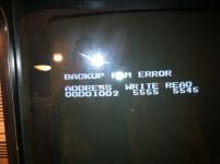
I have had this 4 slot board in storage for a while now since I never had the patience to fix it until now. I am getting this error:
Anyone has any idea what ram chip could be causing this?
I have searched around but I have not found anyone with the same exact error.
Thanks,
I have had this 4 slot board in storage for a while now since I never had the patience to fix it until now. I am getting this error:
Anyone has any idea what ram chip could be causing this?
I have searched around but I have not found anyone with the same exact error.
Thanks,
Attachments
Last edited:


 I don't know what an indent refers to. That link also isn't taking me anywhere.
") but what I'm saying is I don't know which pins on the HC32 I need to check against those on the backup RAM.
but what I'm saying is I don't know which pins on the HC32 I need to check against those on the backup RAM.