PC Engine Coregrafx LED power light mod

MtothaJ

Host for Orochi
10 Year Member
Joined
Apr 15, 2013
Posts
756
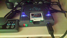
I was meaning to add a power light to the PC Engine Coregrafx and finally got around to it today. This is the end result:
2015-07-18 17.50.10.jpg

Looks pretty good IMHO but your thoughts etc. as always are welcome. If anybody is interested I took some pics while I was doing the mod so I can post them here.

While I was at it I also gave the case a good wash, modded the DIN connector / scart plug wiring for the correct AV selection / 4:3 aspect ratio switching and tidied up the wiring going to Broken's RGB amp (nothing major, just trimmed the excess wiring).

BTW does anybody know where I can get the extension port cover from?
 
Last edited:

MtothaJ

Host for Orochi
10 Year Member
Joined
Apr 15, 2013
Posts
756
Haha I like it! Looks good.

Thanks Todd, can't tell you how happy I am with the RGB amp so once again many thanks for that.
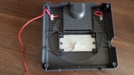
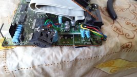
As for the LED mod its pretty simple, below is my wiring:

2015-07-18 15.26.37.jpg

Basically 2 blue LED's feeding off the 9V DC and connected with a 150ohm resistor. The ground is connected by placing that fork thing under the screw on the underside of the board. The LED's are firmly held in place by two sided tape - the case wasn't in any way cut / altered, so this is fully reversible. The light is pretty cool shining symmetrically from under the vents on both sides of the machine.

As for the 4:3 aspect switching I basically used the same 9V solder point on the board as for the LED and routed that to the DIN connector instead of the standard 5V. Then in the scart plug all I did was change the stock (I think) 180ohm resistor across pins 8 & 16 for a 330ohm one and this works perfectly.

So pretty much a fully modded PC Engine - RGB, power on LEDs, RGB input selection and aspect ratio switching enabled and the controller wired with a cable allowing the plugging in of a db15 compatible arcade stick ;)
 
Last edited:

SmokeMonster

Morden's Lackey
Joined
Jan 25, 2014
Posts
365
I normally don't like LED mods at all, but that is a great looking effect. How do you control the aspect ratio switching? You run 9V to the DIN connector instead of 5V, isn't that dangerous?
 

MtothaJ

Host for Orochi
10 Year Member
Joined
Apr 15, 2013
Posts
756
I normally don't like LED mods at all, but that is a great looking effect. How do you control the aspect ratio switching? You run 9V to the DIN connector instead of 5V, isn't that dangerous?

A feature of using RGB on a Scart equipped consumer TV is auto input and aspect ratio selection and RGB mode selection. This realized through passing the appropriate voltage through Pin 8 (0-2V = off, 5-8V = on/16:9, 9-12 V = on/4:3) and Pin 16 (0-0.4V composite, 1-3V = RGB). The obvious choice for retro systems is 4:3 but for systems wired to output only 5V one is by default stuck with 16:9 and then has to manually select 4:3 by way of the TV remote - annoying. Just to emphasis this concerns Scart TV's - if your using a PVM / BVM then equally well you can just ignore connecting anything to Pin 8 & 16 since the above selections are accomplished manually by way of buttons on the actual monitor.
So yeah, I am running 9V through the DIN for pin 8 and reducing that to c.a. 3V by way of the resistor for Pin 16. No danger in that at all - stock SNES or N64 PAL output 12V through Pin 8, it part of Scart specification.
Obviously, I disconnected the 5V that was going there initially - did that by way of desoldering the din connector, clipping the peg that was going through the via, isolating both the via and the connector with a small piece of electric tape and then soldering the din connector back on and running the 9V to the connector out the back in much the same fashion as the R, G and B lines are connected.

2015-07-18 14.05.34.jpg

Even though this took longer (but it needn't had if I did this at the same time as installing the amp) I didn't want to cut any traces on the board, since damaging the OEM hardware when there is a cleaner / non invasive option available would be poor and lazy workmanship.
 
Last edited:

SmokeMonster

Morden's Lackey
Joined
Jan 25, 2014
Posts
365
Thanks for the info. Can I force 4:3 by running 9v through Pin 8 on a GBS-8200 or those common Scart-to-HDMI converters? That would be stellar.
 

MtothaJ

Host for Orochi
10 Year Member
Joined
Apr 15, 2013
Posts
756
Thanks for the info. Can I force 4:3 by running 9v through Pin 8 on a GBS-8200 or those common Scart-to-HDMI converters? That would be stellar.

I have no experience with those so can't help unfortunately.
 

MtothaJ

Host for Orochi
10 Year Member
Joined
Apr 15, 2013
Posts
756
Supergrafx!

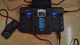
Did pretty much the same mod on the Super Grafx:

2016-08-05 20.05.37.jpg

Colour nicely matches the blue writing on the console - if I ever get a Core Grafx 2 than going to do this mod with orange LEDs :glee:
 

Atro

Who?,
20 Year Member
Joined
Jan 30, 2002
Posts
9,213
You don't need to mod the console to output direct 4:3 aspect ratio.

You can also build an external small circuit to boost 5v to 10v. Put in a box and you're good to go.
I had a specific schematic for Sega Consoles somewhere that I cannot find. I remember it using 2 diodes and an very small IC.
It was actually pretty easy to build.

It's the same principle for other consoles.

Btw, I like more the led mod on the SGFx. Nicely done :)
 

MtothaJ

Host for Orochi
10 Year Member
Joined
Apr 15, 2013
Posts
756
You don't need to mod the console to output direct 4:3 aspect ratio.

You can also build an external small circuit to boost 5v to 10v. Put in a box and you're good to go.
I had a specific schematic for Sega Consoles somewhere that I cannot find. I remember it using 2 diodes and an very small IC.
It was actually pretty easy to build.

It's the same principle for other consoles.

Btw, I like more the led mod on the SGFx. Nicely done :)

Thanks. There is no mod to the console here as such - basically substituting the 5V din output with the 9V from the power supply. Sure you can built a circuit or adapt an existing one (e.g. official Sega Megadrive 1 and 2 scart cables with the voltage boost circuit) but there is little point when the appropriate voltage is already in the console.
 
Top