Want to add trim pots to AES Neobitz mod

gtdoering

New Challenger
Joined
Apr 29, 2014
Posts
53
So I was sitting on my duff, and pondering just how I might be able to squeeze out a little better picture out of my modded AES that I just finished adding a Neobitz encoder to. I was wondering if I could remove the 120ohm resistors I have installed on the RGB lines, and replace them with some trim pots. I've never wired trim pots before and was curious if anyone out there had ever done this or knows a good brand of trim pots that I could use. I've seen this kind of mod done on some consolized MVS's (I'm currently building one myself). I noticed that most trim pots out there have tree legs on them. Does that mean that one leg is ground and the other two are in/out and if so which one is what. I'm having trouble getting good info on this as it seems not all trim pots are made equal.
 

miisalo

Astra Superstar
Joined
Jan 3, 2014
Posts
669
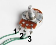
acp_pot_id.jpg

Three leg pot works so that resistance between 1 and 2 rises from 0 to pot's value when you turn pot clockwise and falls between 2 and 3 from pot's value to 0. Resistance between 1 and 3 is the pot's value.

You can use pot as adjustable resistor connecting two pins, 1 and 2 or 2 and 3.

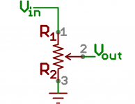
Normally pots are used as voltage divider. Signal in is connected to pin 1, signal out to 2 and 3 acts as pull down to ground.

511ac8f5ce395f5846000000.png

In your case I think you are using them as voltage dividers.

Oh, forgot to mention that you might want to swap 1 and 3. Then trim pot turned fully clockwise = brightest and fully counter clockwise = darkest.
 
Last edited:

gtdoering

New Challenger
Joined
Apr 29, 2014
Posts
53
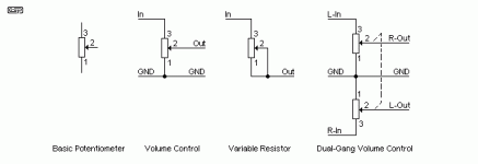
So if I go with example three in this diagram I will get the desired effect of dim to bright? just want to be sure I understand correctly. I know the diagram uses improper symbols and that the Pot should be represented with a zig-zaging line to represent resistance, but this image just made sense.
pots-f6.gif
 
Last edited:

JMKurtz

Tech Support Moderator,
20 Year Member
Joined
Aug 12, 2000
Posts
1,654
There are three holes right by the 120ohm resistors. Once you remove those, you can solder the three wires of the pot to those three holes.

I used to have drop-in parts for that but he pot that I had used when I originally added the POTs to the PCB are no longer manufactured. :/
 
Top