No background in games

Iroshi*Nagasaki

Kabuki Klasher
Joined
Mar 20, 2004
Posts
125
Hey Guys, it's been a while since I posted here, but I have come out of retirement with a new problem. I have a consolized two slot which has been giving me the following problem: missing backgrounds. All of my carts are clean and the system itself is very clean. So I don't think is dirt, any ideas of what is causing it? I have a attached two images for reference.

Any help, would be greatly appreciated!
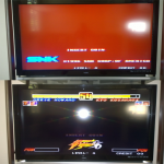
no backgrounds.png
 

Xian Xi

JammaNationX,
15 Year Member
Joined
Dec 1, 2005
Posts
27,750
Check the area around the ZMC2 for any broken traces or corrosion.
 

Iroshi*Nagasaki

Kabuki Klasher
Joined
Mar 20, 2004
Posts
125
Indeed there was some corrosion on the contacts of the chip. I cleaned it well, yet the problem still persists! Any other ideas of what is causing it?
 

BIG BEAR

SHOCKbox Developer,
20 Year Member
Joined
Dec 14, 2001
Posts
8,237
You need to re-flow the solder on the ZMC2 or replace it.
BB
 

fremen

Hardened Shock Trooper
Joined
Aug 4, 2010
Posts
433
Hi dudes,

Iroshi as XX recommended you, looking for any broken traces and repair them, clean the zone is not enough.

Un saludo
 

bustedstr8

Trollbox Trade Federation,
Joined
Oct 15, 2007
Posts
943
It could be the clock for the C-Rom latches. I had a Tengai that lost all sprites when the clock signal from the custom chip died. This clocked a pair of LS273.

Looks like the LSPC2 outputs clock for C-Rom latches from pin 103 (PK1) this is then inverted by a LS04 and sent to the NEO273 on the cart.

The schematic I found is messy and I couldn't read the location of the LS04, but if you follow the circuit from LSPC2 pin103 you should be able to find which gate on the LS04 is used and check the clock input and output.


Spoiler:
Lspc2-a2_pinout.png
 

GadgetUK

Ace Ghost Pilot
Joined
Sep 27, 2013
Posts
1,323
It could be the clock for the C-Rom latches. I had a Tengai that lost all sprites when the clock signal from the custom chip died. This clocked a pair of LS273.

Looks like the LSPC2 outputs clock for C-Rom latches from pin 103 (PK1) this is then inverted by a LS04 and sent to the NEO273 on the cart.

The schematic I found is messy and I couldn't read the location of the LS04, but if you follow the circuit from LSPC2 pin103 you should be able to find which gate on the LS04 is used and check the clock input and output.


Spoiler:
Lspc2-a2_pinout.png
That's great info! Nice to see posts like this on here =)
 

Iroshi*Nagasaki

Kabuki Klasher
Joined
Mar 20, 2004
Posts
125
Thanks for all the help guys, i'm currently in the process of checking all traces before looking for other options. I have to remove the upper case first so I can have more space and work without it interfering.
 
Top