MV-1FZ backup ram error

MtothaJ

Host for Orochi
10 Year Member
Joined
Apr 15, 2013
Posts
756
When buying a MVS cart the seller threw in a untested MV-1FZ board.

When I connected the board to the supergun and powered on with no game it is reporting a Backup Ram Error - WRITE 0000 READ 1000

Can anybody assist in helping to diagnose this fault? At my disposal I have my working MV-1FZ board with Unibios which I can drop into the other board.

If I understand correctly it may mean the ram chips need to be changed but equally well it could just be a trace problem on the board.

Can anybody point me to what pin on which chip I can try bridging (and with what) to rule out the trace problem?

WRITE 0000 = 00000000
READ 1000 = 00010000

If I am correct the problem is the 5th bit - can you advise what data pin and on which chip this corresponds to and to which pin on the cpu this should go?

Any other ideas are welcome.
 

Xian Xi

JammaNationX,
15 Year Member
Joined
Dec 1, 2005
Posts
27,750
Test to make sure that /WE and /CE are active low. If you are getting 0s that usual means a lack of control signals. You can check the LS32 in the backup area as well as the transistor(Q1 I think) on the underside of the board.
 

MtothaJ

Host for Orochi
10 Year Member
Joined
Apr 15, 2013
Posts
756
Xian, can you elaborate what are the /WE and /CE you are referring to? I'm just a noob but pretty sure I can fix this with some guidance. Anyhow I understand I'll be needing a logic probe. Cannot seem to find LS32 also - any advice on this?

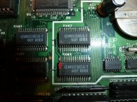
Below I have posted a picture of the Backup Ram area of the board:

mvs board.JPG

To me it seems there may be some damage on the trace pointed to by the red arrow on the RAM4 chip. Any ideas to what I could jumper this pin to?
 

bustedstr8

Trollbox Trade Federation,
Joined
Oct 15, 2007
Posts
943
This board uses a 74HC32 instead of LS32. That area looks rough...the solder pad for pin 9 looks like it got ripped off.

That corroded Vcc pin on the ram could very likely be the problem and the /WE could be lifted as well.
You need to do some continuity checks in those areas.

AS6C62256-pinout.jpg
 

MtothaJ

Host for Orochi
10 Year Member
Joined
Apr 15, 2013
Posts
756
This board uses a 74HC32 instead of LS32. That area looks rough...the solder pad for pin 9 looks like it got ripped off.

That corroded Vcc pin on the ram could very likely be the problem and the /WE could be lifted as well.
You need to do some continuity checks in those areas.

AS6C62256-pinout.jpg

As for the 74HC32 there seems to be continuity between every pin on that chip and the CPU.
For the RAM3 and RAM4 there is continuity between the two ram chips. I checked the Vcc pin and while that area of the board has for sure seen better days there is continuity between the Vcc pins of RAM3 and RAM4.
I also had a look at this post: http://www.retrocomputermuseum.co.uk/forum/index.php?topic=3410.0
Going on that analogy I need to look at the 5th bit (reading right-to-left) and the corresponding pin - but have no idea what that could be.

BTW really appreciate both of you guys taking the time to help out.
 
Last edited:

Xian Xi

JammaNationX,
15 Year Member
Joined
Dec 1, 2005
Posts
27,750
It's possible you may need to replace those RAM chips if the corrosion is near the body and may have moved inside the chip itself severing the connection for the /WE pin.
 

MtothaJ

Host for Orochi
10 Year Member
Joined
Apr 15, 2013
Posts
756
It's possible you may need to replace those RAM chips if the corrosion is near the body and may have moved inside the chip itself severing the connection for the /WE pin.

From what I am seeing so far, despite that area of the board being a bit ropey there seems to be continuity so traces are probably fine.
Any place in particular I can get these replacement chips from?
 

bustedstr8

Trollbox Trade Federation,
Joined
Oct 15, 2007
Posts
943
The 5th bit on the high ram is D12. D12 on the 68K data bus is shared by the other high ram and bios(SP1)

So check pin16 of Ram4 to the other high ram pin 16 and to D12 on the 68K and SP1


I dunno if there are better scans out there...James may have one

https://wiki.neogeodev.org/images/c/cc/Mv1fs-page1.jpg
 
Last edited:

GadgetUK

Ace Ghost Pilot
Joined
Sep 27, 2013
Posts
1,323
I've used these without problem:-

http://www.ebay.co.uk/itm/351032749695

I've also done a vid on YouTube covering this. I showed a simple unorthodox way to remove the chips if you've not got a hot air rework station. Used chip qwik as well in other vids. Worth testing the HC32 with a logic probe like I did, just to rule it out.
 

MtothaJ

Host for Orochi
10 Year Member
Joined
Apr 15, 2013
Posts
756
The 5th bit on the high ram is D12. D12 on the 68K data bus is shared by the other high ram and bios(SP1)

So check pin16 of Ram4 to the other high ram pin 16 and to D12 on the 68K and SP1


I dunno if there are better scans out there...James may have one

https://wiki.neogeodev.org/images/c/cc/Mv1fs-page1.jpg

I checked and there seems to be continuity between pins 16 (top row, second from the right) of RAM3 and RAM4 and pin 12 of the CPU as well as with the BIOS. I say 'it seems' since the multimeter is not buzzing to indicate outright continuity but when the two probes are placed at the above mentioned points the scale keeps increasing to 2000 and then shows the default 1 (as in no continuity) - does this seem right? The thing is I am getting similar readings / behaviour if I touch any two pretty much random points on the board so not entirely sure what is going on.
I will also want to change the battery - in fact I have these on hand but will wait with this for the timebeing since this does not seem to be the root of the problem. The area under the foam sticker on the back of the board under the backup ram area looks entirely fine.
 

bustedstr8

Trollbox Trade Federation,
Joined
Oct 15, 2007
Posts
943
D12-Data12 on the 68000 is pin57...so something is off with your meter. Try testing on the ohm setting. Continuity should show as .1 - .5 ohm
 

MtothaJ

Host for Orochi
10 Year Member
Joined
Apr 15, 2013
Posts
756
D12-Data12 on the 68000 is pin57...so something is off with your meter. Try testing on the ohm setting. Continuity should show as .1 - .5 ohm

Getting the following readings:
- CPU pin 57 -> RAM3 pin 16 - 0.407
- CPU pin 57 -> RAM4 pin 16 - 0.404
- RAM3 pin 16 -> RAM4 pin 16 - 1.561 (???)

Do you think there is any point in trying to jumper wire together the two pin 16's on RAM3 and RAM4?
 

bustedstr8

Trollbox Trade Federation,
Joined
Oct 15, 2007
Posts
943
Getting the following readings:
- CPU pin 57 -> RAM3 pin 16 - 0.407
- CPU pin 57 -> RAM4 pin 16 - 0.404
- RAM3 pin 16 -> RAM4 pin 16 - 1.561 (???)

Do you think there is any point in trying to jumper wire together the two pin 16's on RAM3 and RAM4?

Something is still odd with your readings

It should read
- CPU pin 57 -> RAM3 pin 16 - Open
- CPU pin 57 -> RAM4 pin 16 - 0.404
- RAM3 pin 16 -> RAM4 pin 16 - Open

Do you think there is any point in trying to jumper wire together the two pin 16's on RAM3 and RAM4? No, one is D4 and the other is D12

What ohm reading do you get with the leads together?
 
Last edited:

MtothaJ

Host for Orochi
10 Year Member
Joined
Apr 15, 2013
Posts
756
Something is still odd with your readings

It should read
- CPU pin 57 -> RAM3 pin 16 - Open
- CPU pin 57 -> RAM4 pin 16 - 0.404
- RAM3 pin 16 -> RAM4 pin 16 - Open

Do you think there is any point in trying to jumper wire together the two pin 16's on RAM3 and RAM4? No, one is D4 and the other is D12

What ohm reading do you get with the leads together?

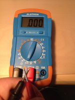
With the two leads of the meter together in ohm mode I am getting 0.000:

IMG_0176.JPG

If I switch to buzzer mode then it buzzes.

Just this morning I checked again the above points and now got the following readings
- CPU pin 57 -> RAM3 pin 16 - 0.850
- CPU pin 57 -> RAM4 pin 16 - 0.868
- RAM3 pin 16 -> RAM4 pin 16 - 1.576 (same)

So the only consistent reading is RAM3 pin 16 -> RAM4 pin 16 - should the meter be replaced or is there any plausible explanation for the difference in readings over the scope of just a couple of hours?
 

bustedstr8

Trollbox Trade Federation,
Joined
Oct 15, 2007
Posts
943
I'm not familiar with that meter, but if you used the 2K setting I would think your readings are in the thousands resolution. So that would be 850ohm, 868ohm an 1576ohm.

I just looked at Womble's post and realized that board uses a 68QFP 68K. I assumed it used a 64SDIP...woops:-J

So D12 is pin 61 on that package. Try using the 200ohm setting also.

MC68000-MC68HC000-MC68010-68-QP-Pinout.png
 

MtothaJ

Host for Orochi
10 Year Member
Joined
Apr 15, 2013
Posts
756
I'm not familiar with that meter, but if you used the 2K setting I would think your readings are in the thousands resolution. So that would be 850ohm, 868ohm an 1576ohm.

I just looked at Womble's post and realized that board uses a 68QFP 68K. I assumed it used a 64SDIP...woops:-J

So D12 is pin 61 on that package. Try using the 200ohm setting also.

MC68000-MC68HC000-MC68010-68-QP-Pinout.png

Just this morning I tried probing certain pins on the CPU and RAM3 / RAM4 chips with a piece of jump wire. Results varied but:
- on quite a few occassions I got to the 'stuck on green' screen (i.e. from what I understand passed the memory test and failed the calendar test)
- on about 3 occasions I managed to make it to the crosshatch screen

Consequently, my feeling is that there are probably at least two traces to fix - one pertaining to the RAM the other to the NEC D4990 chip.
When I was poking around earlier I did not understand the significance of the stuck on green screen - thought it was just a glitch and was expecting the crosshatch.
So the sensible action plan for the moment would be:
- determine whether it is possible to bridge a CPU pin with that of the RAM so that the board goes to 'stuck on green' and jumper wire those two pins
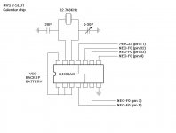
- with the above done, go and try to diagnose the NEC D4990, using the below pinout:

2slotcalendarak9.jpg

BTW really appreciate the CPU diagram, I am currently away for an extended weekend, but once I come back I will use all of the diagrams which I have so far to see if I can resolve this. Seeing the crosshatch pop up kind of makes me think the solution is perhaps within reach - as mentioned my gut feeling is that while it could be the memory chips or something else it is probably down to track rot on 2 tracks - I will get back as soon as I come back and am able to do some testing.
 
Last edited:

MtothaJ

Host for Orochi
10 Year Member
Joined
Apr 15, 2013
Posts
756
I updated my earlier post above with a schematic for the calendar chip and also some further info concerning diagnosing the fault 'stuck on green' and crosshatch.
 
Last edited:

MtothaJ

Host for Orochi
10 Year Member
Joined
Apr 15, 2013
Posts
756
Had some time to look at this again:
- ignore my earlier comments regarding continuity - it turned out I got the numbering of the pins on the ram chips wrong (doh!) hence the strange results.
- knowing which pin is which, I buzzed through all the pins on RAM3 and RAM4 with the multimeter using the pinout as per the info available on e.g. the GadgetUK164 YouTube channel and all the respective connections are in place
- D4990 connectivity is also fine
- The errors which I predominently now get are:
WRITE 5555 READ 1555
and sometimes WRITE AAAA READ AA00
Any ideas?
- I also replaced the battery since the old one was dead and wasn't holding any charge (but was not leaking). Left the board plugged in to charge overnight, however this is unlikely to make much of a difference with regard to the above error.

At this point I think it is time to replace the RAM chips. Since the chips are surface mounted I am a bit concerned not to fcuk anything up, but can't think of anything else to check / rule out.
 

BIG BEAR

SHOCKbox Developer,
20 Year Member
Joined
Dec 14, 2001
Posts
8,237
What is this the BACKUP RAM area? If so, it's a trace somewhere in that area.
BB
 

bustedstr8

Trollbox Trade Federation,
Joined
Oct 15, 2007
Posts
943
Where does the error occur?
If it's at $00D00000 the problem can be a bad ram or from missing signals. (broken trace, bad solder joint, bad TTL like the LS32 or some other board damage)
If it's $00D00001 to $00D0FFFF it's almost always a bad ram chip.
 

MtothaJ

Host for Orochi
10 Year Member
Joined
Apr 15, 2013
Posts
756
Where does the error occur?
If it's at $00D00000 the problem can be a bad ram or from missing signals. (broken trace, bad solder joint, bad TTL like the LS32 or some other board damage)
If it's $00D00001 to $00D0FFFF it's almost always a bad ram chip.

5555 1555 -> 00D04EA2
AAAA AA00 -> 00D00000

As for the HC32, I do not have the pinout for this chip but the lines that I did check from the RAM3, RAM4 and D4990 pinouts connected fine.
 

MtothaJ

Host for Orochi
10 Year Member
Joined
Apr 15, 2013
Posts
756
http://pdf.dzsc.com/20130115/74HC32DR2G_2283426.pdf

Look at the pinout, and logical diagram to match OR gates to pinout. Check inputs to each gate vs output for that gate on logic probe or multimeter. If one or more of the 2 inputs is high you should get a high output.

Thanks, I will need to get a logic probe and look into this.

For the time being my understanding of the errors is as follows:
- READ 5555 WRITE 1555 -> problem with the 7th bit on the high ram (RAM4?) - need to check pin 18 on RAM4 (and RAM3 to be on the safe side). Done this already, but will have another go just to be sure.
- READ AAAA WRITE AA00 -> no writing taking place on low ram (RAM3?) - need to check WE, OE, CE - pins 27, 22 and 20 and possibly VCC / Ground to be sure, also for RAM4. Again, done this already but will check again. Only started getting this error recently and it pops up only every so often.

As mentioned by probing more or less at random with a piece of wire between the CPU and the RAM3 / 4 I managed to get to the 'stuck on green' screen and also on a couple of occasions got the cross hatch to appear. Wasn't able to repeat this by just connecting two pins though, so I would imagine I just fooled the board by maybe connecting a read and write together or something.
 
Last edited:

GadgetUK

Ace Ghost Pilot
Joined
Sep 27, 2013
Posts
1,323
Since it's just that bit I am guessing its either a track or the SRAM.
 
Top