mikejmoffitt
Mickey's Coach

- Joined
- Feb 6, 2014
- Posts
- 578
I've written about this project a little in the TV compatibility thread, and a little more on my site - it was in hackaday not long ago - but I think this community is probably the one that would understand and appreciate it the most so I think I'll do a more detailed writeup here.
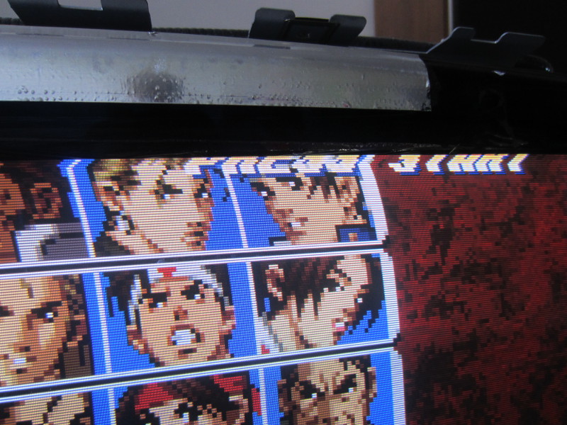
Here is a nicely scaled KoF99:
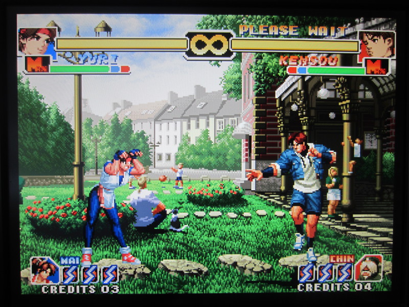
What is NeoVGA?
NeoVGA is an FPGA-based video scaling solution for the Neo-Geo MVS and AES systems. It implements a classic line-doubling method, which produces far less than a single millisecond of lag. Unlike many line doublers, this one operates entirely in the digital domain up until the output stage. It uses the CPU clock, which is double the Neo-Geo's pixel clock to latch in pixel data and generate its output. This means that the timings are exactly double that of the original MVS timings.
The primary advantage over other solutions is that data is captured digitally, so there are no uneven edges from the analogue signal not being perfectly quantized to the buffer it is being captured to.

Principles of Operation Part 1: RGB Video Timings
The Neo-Geo video timings are similar to many other 15KHz RGB-compatible arcade and home console systems of the time. Within 1/60th of a second, a single frame of video is displayed - much like a modern monitor using DVI, HDMI, or VGA. The difference here comes from the horizontal sync rate, which in the end boils down to how many lines are being displayed. The term "15KHz RGB" refers to the fact that a new line is drawn with a frequency of 15KHz, or 15000 times per second. This number isn't exact - we can do the math to determine the true horizontal refresh rate of the Neo-Geo. While there are 224 active display lines, there are blank lines above and below the active frame area that count for the sake of timing. From Charles MacDonald's mvstech.txt we can learn that the Neo-Geo produces 264 lines per frame. 264 lines * 60 frames per second = 15840 lines per second. The horizontal sync signal exists to indicate the end of a display line, so there will be 15840 pulses per second - or 15.84KHz. That is the true horizontal refresh of the Neo-Geo. From the Neo-Geo Development Wiki is this image:

The Neo-Geo isn't perfectly refreshing at 60Hz, either - it is a little lower, 59.18Hz. This is within tolerances of most flat panel displays, and just about every CRT monitor ever made.
Principles Of Operation Part 2: VGA Timings
You may ask, "It is refreshing at 60Hz, and the resolution is so low - why can't a new display handle it already?"
There are a few reasons. The simplest is merely clerical - older JAMMA based systems, and most consoles, output their sync information (Hsync and Vsync) through a single pin called Csync, or Composite Sync. Sync information is usually active-low, often called Negative Sync. This is a misleading name - you might expect it to be at -5V at some point. What this means is that the line is a logic HIGH when inactive, and gets pulled to a logic LOW when the sync happens. These values are 5V and 0V on the Neo-Geo, specifically. The Csync line is simply Vsync and Hsync XORed together. They can be separated without too much work later on. The point here is that the VGA standard expects Hsync and Vsync to be separate already, on pins 13 and 14 respectively, of the VGA connector.
However, even if the sync signals are split, there remains the far larger complication of the timings. A VGA monitor, by standards, will only accept a horizontal sync of ~30KHz and up (for SVGA, XGA, etc. monitors). Attempts to give it low-resolution images will typically result in nothing happening, or if it's a nicer monitor, it will say "out of range" or something like that. Sometimes you'll find an oddball monitor that will take 15KHz RGB with Csync through the VGA port, but it's not common. A great example is the Samsung 940Be. Click for a video of it running a Sega Genesis in both 240p and 480i mode. We can't rely on this, however.
So, let's consider what it means for VGA to be rendered at 30KHz horizontal refresh. The VGA standard resolution is 640x480. As VGA is analogue, we can more or less ignore the horizontal resolution of 640, as that's really up to the device's pixel clock. A line is really just generated by a constantly moving electron beam whose intensity is modulated by the R, G, or B signal coming in at the right time. If you are unfamiliar with the principles of how a CRT monitor displays, you may find it helpful to learn about it through some research. It will help you understand modern ones too, as their timings are based on CRT timings still - even HDMI. The point is, the monitor is relatively agnostic of the horizontal resolution, though digital ones will attempt to determine the source pixel clock to quantize the pixels nicely into the pixel grid.
We care about the 480 lines from the VGA spec. If 480 lines are displayed in the same time as our Neo-Geo's roughly 320x240 display, that means that each VGA line comes out twice as fast as a single Neo-Geo one. The term "line doubling" may become much clearer now.
Principles Of Operation Part 3: Line Buffering
Most scaling devices, even really nice ones like the XRGB-Mini Framemeister, sample an entire frame from the RGB source to a buffer, scale that buffer to the output resolution with or without additional effects like dimension adjustment and scanlines, then render that out to the display. In a good one, the vertical sync is locked, so there is never tearing from the two devices (source, and the output device) getting out of sync. However, this will guarantee a certain amount of lag that may approach one or more frames of time. For many this is fine, but considering that the display itself will often do its own display processing and add more lag, it would be nice to not add to the chain.
The other approach is line doubling. Yes, I keep saying this, but here I'm going to finally explain it. Basically, armed with the knowledge that a VGA line can be exactly double that of the RGB one and fall within the spec, we can use the following technique. Let's use a hypothetical variable for time, t[/y]. At t = 0, the RGB line has just begun. At t = 1, the RGB line is finished. From 0 <= t <= 1, we capture the RGB line into a buffer the size of a single line. Since I am doing this digitally, this means 5 + 5 + 5 + 2 bits per pixel, * 384 (for the whole line, including blanking period). This comes from 5 bits of red, green, and blue, plus the SHAD and DAK bits.
So, we've captured an entire line into the buffer. We will have two buffers, however, and alternate between them for every other line - one even buffer, and one odd buffer. Let's call them buffers A and B. As the odd buffer is captured, the even buffer is rendered out to the VGA output twice, at double the speed. So, at t = 0.5, the RGB output is halfway through capturing a line into buffer A, but the VGA output has just finished rendering an entire line from buffer B. It will then render buffer B again from the start from t = 0.5 to t = 1.0. Then, A and B will swap roles, and this process repeats forever. That's the basic principle of line doubling.
The challenge with this design typically comes from getting the timings just right, as off of a JAMMA edge all you have for timing is the Csync information. From that you must determine a input and output pixel clock, and new sync info. Then, you must also do an analogue to digital conversion from the RGB signals present. On the Neo-Geo (and many other arcade boards), this information is available in pure digital format before the JAMMA edge. I mentioned above the 17 bits needed for a single pixel, but timing is the more important thing. The pixel clock is 6MHz - the rate at which an RGB pixel is generated. The CPU clock happens to be 12MHz, which is exactly double the pixel clock (both are divisions of the 24MHz master clock). Since I am trying to double our pixel timings, I will take advantage of this already doubled pixel clock and use it as the clock in my design. During the capture phase, I capture a single pixel every other 12Mhz clock (to match the 6MHz rate coming from the system), while during the display phase I output a new pixel every 12MHz pulse.
The result is that the captured information is perfect. If displayed properly it is indistinguishable from an emulator. Since I'm using a 12MHz pixel clock, I'm really generating 320x480 video - half the resolution of VGA. That's fine, though - actually perfect - as that is what an exactly line doubled Neo-Geo should be.

Stuff That's Tricky
It turns out that while a CRT-based VGA monitor which operates primarily in the analogue domain is pretty allowing in what you give it, a lot of modern displays are particular about what they want from their VGA timings. I learned a lot about VGA output through this project. A few postulates I learned are listed below:
1. Do not output ANYTHING during the sync pulse of a line.
During the horizontal syncing period, and maybe some of the back porch, the display sees the voltage level on the RGB lines and clamps to them, meaning it basically treats that value as 0. So, if you are outputting 0.2V on your red line during that time that it should be blank, the red will be darker for that line. So, that needs to be lined up properly! The same seems to go during the vertical sync, though I haven't determined exactly how standard that is.
2. Continue horizontal sync pulses during Vsync.
It was hard to figure out whether Hsync should occur during Vsync or not. A few dell LCD monitors, and my big old sony CRT monitor sure didn't care, so I disabled it during Vsync. Then, a few monitors later, my HP 23xi would work, but intermittently drop the image. A few other monitors would show nothing. Turns out you should have it - I put it back, and now the HP monitor is 100% stable.
3. The Neo-Geo's timings are a little odd, and so are the resulting VGA ones.
It's hard to get the timings perfect in general, but for the Neo-Geo it's extra odd. Some VGA monitors just aren't okay with it. This is a great reason to go with the full-frame buffer solution that most scalers do, as it lets you deal with this fact. So, this project may just not be compatible with all LCDs. I've had great luck on almost every HDTV with VGA I've tested, but I can't guarantee it works on all.
4. The Neo-Geo's CPU clock is ugly.
I scoped out the CPU clock on my MVS systems (MV-1C, MV-1, MV-4) and all of them are very noisy and non-square. It should be a nice square wave pulse, but it is in fact an ugly wave that is almost sinusoidal. Fine for the 68000, I suppose, but it caused some missed / repeated clocks on my FPGA dev boards I tried. A Schmidt trigger (74HC74) solved this issue, but it had be going crazy for a little while trying to determine what the hell was wrong with my design.
5. DAK and SHAD are poorly documented.
The Neo-Geo output has a pretty primitive resistor ladder DAC. While I am capturing SHAD and DAK, I'm not 100% sure what to even do with them. Right now I have determind which one is supposed to dim the screen (I test by writing a value to 0x3A0011 and 0x3A0001 and it does work) but within the 8-bit VGA DAC I'm using it won't really look correct. Eventually I plan on just building a duplicate of the original Neo-Geo DAC for output so it will be perfect. A non-issue, but I found it a little odd.
6. Your Vsync should be exactly two lines of time for 480 lines.
I had it a little too long, and the display did some weird skewing stuff on my CRT. On a Sony LCD television it was even weirder:
I made it two lines (768 CPU clock cycles) and it resolved itself.
Future Work
So, from here I'm not totally sure where I want to go. Right now the project is fairly stable, and even has a few tiny features like variable-intensity scanlines. However, once every now and then it will power up in a very odd state where the pixels will be captured all dirty, and flicker a bit on changing edges. I'm not sure of the cause. The next thing I will be doing is setting up a proper level converter, as right now I am passing my 5V levels into my 3.3V FPGA system, which is not great and I'm sure could cause issues in the future (though it is supposed to be 5V tolerant to some extent...). Perhaps this will improve things. Right now each line is a huge 384-position 17-bit shift register, which is not a great design, but it is what I am doing because I can not get block memory to be generated properly from ISE's IP core creator. My version of ISE is very old but nothing newer works on here, so it may be an actual bug.
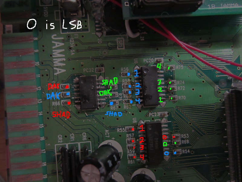
I think it would be neat to develop a board in the same spirit as the NESRGB board - something for ~$100 that people who are really into their Neo-Geo MVS or AES systems could install in their board with some precise soldering, and enjoy a video output superior to current solutions. There are 22 lines that need to be soldered for it to work. It's not that bad, fortunately everything is pretty clearly laid out on the system. I haven't an AES so I have not tested there, but I do not see why it would not work.
I don't really know what is needed to go from the FPGA dev board to a proper separate board, though. If anyone is more experienced with this and has some pointers / recommendations, that would be appreciated. It doesn't use a lot of the FPGA's resources, so a smaller and cheaper one could be used. Certainly it will be many times cheaper than an XRGB system if finished. Some will cry out, "the GBS8200 works fine!" but I think if anyone is actually happy with a GBS8200 then they don't care much for video quality in the first place or don't want anything more expensive. I'd like for this to be $100 or lower. I'm using a Virtex-II Pro, which was new in 2003. Surely there are many old-stock or bare ones lying about, so this shouldn't have to be too expensive if a board was really produced.
Oh, here's a VERY high resolution of Windjammers with the 50% scanlines enabled: http://mikejmoffitt.com/img/neovga/v2psetup/wjammers.jpg
Anyway, if you have questions or suggestions I'd like to hear them. I'm not totally sure where to take this project from here, so any expressions of interest would be good motivation / a means to determine the future of it.
Here is a nicely scaled KoF99:
What is NeoVGA?
NeoVGA is an FPGA-based video scaling solution for the Neo-Geo MVS and AES systems. It implements a classic line-doubling method, which produces far less than a single millisecond of lag. Unlike many line doublers, this one operates entirely in the digital domain up until the output stage. It uses the CPU clock, which is double the Neo-Geo's pixel clock to latch in pixel data and generate its output. This means that the timings are exactly double that of the original MVS timings.
The primary advantage over other solutions is that data is captured digitally, so there are no uneven edges from the analogue signal not being perfectly quantized to the buffer it is being captured to.
Principles of Operation Part 1: RGB Video Timings
The Neo-Geo video timings are similar to many other 15KHz RGB-compatible arcade and home console systems of the time. Within 1/60th of a second, a single frame of video is displayed - much like a modern monitor using DVI, HDMI, or VGA. The difference here comes from the horizontal sync rate, which in the end boils down to how many lines are being displayed. The term "15KHz RGB" refers to the fact that a new line is drawn with a frequency of 15KHz, or 15000 times per second. This number isn't exact - we can do the math to determine the true horizontal refresh rate of the Neo-Geo. While there are 224 active display lines, there are blank lines above and below the active frame area that count for the sake of timing. From Charles MacDonald's mvstech.txt we can learn that the Neo-Geo produces 264 lines per frame. 264 lines * 60 frames per second = 15840 lines per second. The horizontal sync signal exists to indicate the end of a display line, so there will be 15840 pulses per second - or 15.84KHz. That is the true horizontal refresh of the Neo-Geo. From the Neo-Geo Development Wiki is this image:
The Neo-Geo isn't perfectly refreshing at 60Hz, either - it is a little lower, 59.18Hz. This is within tolerances of most flat panel displays, and just about every CRT monitor ever made.
Principles Of Operation Part 2: VGA Timings
You may ask, "It is refreshing at 60Hz, and the resolution is so low - why can't a new display handle it already?"
There are a few reasons. The simplest is merely clerical - older JAMMA based systems, and most consoles, output their sync information (Hsync and Vsync) through a single pin called Csync, or Composite Sync. Sync information is usually active-low, often called Negative Sync. This is a misleading name - you might expect it to be at -5V at some point. What this means is that the line is a logic HIGH when inactive, and gets pulled to a logic LOW when the sync happens. These values are 5V and 0V on the Neo-Geo, specifically. The Csync line is simply Vsync and Hsync XORed together. They can be separated without too much work later on. The point here is that the VGA standard expects Hsync and Vsync to be separate already, on pins 13 and 14 respectively, of the VGA connector.
However, even if the sync signals are split, there remains the far larger complication of the timings. A VGA monitor, by standards, will only accept a horizontal sync of ~30KHz and up (for SVGA, XGA, etc. monitors). Attempts to give it low-resolution images will typically result in nothing happening, or if it's a nicer monitor, it will say "out of range" or something like that. Sometimes you'll find an oddball monitor that will take 15KHz RGB with Csync through the VGA port, but it's not common. A great example is the Samsung 940Be. Click for a video of it running a Sega Genesis in both 240p and 480i mode. We can't rely on this, however.
So, let's consider what it means for VGA to be rendered at 30KHz horizontal refresh. The VGA standard resolution is 640x480. As VGA is analogue, we can more or less ignore the horizontal resolution of 640, as that's really up to the device's pixel clock. A line is really just generated by a constantly moving electron beam whose intensity is modulated by the R, G, or B signal coming in at the right time. If you are unfamiliar with the principles of how a CRT monitor displays, you may find it helpful to learn about it through some research. It will help you understand modern ones too, as their timings are based on CRT timings still - even HDMI. The point is, the monitor is relatively agnostic of the horizontal resolution, though digital ones will attempt to determine the source pixel clock to quantize the pixels nicely into the pixel grid.
We care about the 480 lines from the VGA spec. If 480 lines are displayed in the same time as our Neo-Geo's roughly 320x240 display, that means that each VGA line comes out twice as fast as a single Neo-Geo one. The term "line doubling" may become much clearer now.
Principles Of Operation Part 3: Line Buffering
Most scaling devices, even really nice ones like the XRGB-Mini Framemeister, sample an entire frame from the RGB source to a buffer, scale that buffer to the output resolution with or without additional effects like dimension adjustment and scanlines, then render that out to the display. In a good one, the vertical sync is locked, so there is never tearing from the two devices (source, and the output device) getting out of sync. However, this will guarantee a certain amount of lag that may approach one or more frames of time. For many this is fine, but considering that the display itself will often do its own display processing and add more lag, it would be nice to not add to the chain.
The other approach is line doubling. Yes, I keep saying this, but here I'm going to finally explain it. Basically, armed with the knowledge that a VGA line can be exactly double that of the RGB one and fall within the spec, we can use the following technique. Let's use a hypothetical variable for time, t[/y]. At t = 0, the RGB line has just begun. At t = 1, the RGB line is finished. From 0 <= t <= 1, we capture the RGB line into a buffer the size of a single line. Since I am doing this digitally, this means 5 + 5 + 5 + 2 bits per pixel, * 384 (for the whole line, including blanking period). This comes from 5 bits of red, green, and blue, plus the SHAD and DAK bits.
So, we've captured an entire line into the buffer. We will have two buffers, however, and alternate between them for every other line - one even buffer, and one odd buffer. Let's call them buffers A and B. As the odd buffer is captured, the even buffer is rendered out to the VGA output twice, at double the speed. So, at t = 0.5, the RGB output is halfway through capturing a line into buffer A, but the VGA output has just finished rendering an entire line from buffer B. It will then render buffer B again from the start from t = 0.5 to t = 1.0. Then, A and B will swap roles, and this process repeats forever. That's the basic principle of line doubling.
The challenge with this design typically comes from getting the timings just right, as off of a JAMMA edge all you have for timing is the Csync information. From that you must determine a input and output pixel clock, and new sync info. Then, you must also do an analogue to digital conversion from the RGB signals present. On the Neo-Geo (and many other arcade boards), this information is available in pure digital format before the JAMMA edge. I mentioned above the 17 bits needed for a single pixel, but timing is the more important thing. The pixel clock is 6MHz - the rate at which an RGB pixel is generated. The CPU clock happens to be 12MHz, which is exactly double the pixel clock (both are divisions of the 24MHz master clock). Since I am trying to double our pixel timings, I will take advantage of this already doubled pixel clock and use it as the clock in my design. During the capture phase, I capture a single pixel every other 12Mhz clock (to match the 6MHz rate coming from the system), while during the display phase I output a new pixel every 12MHz pulse.
The result is that the captured information is perfect. If displayed properly it is indistinguishable from an emulator. Since I'm using a 12MHz pixel clock, I'm really generating 320x480 video - half the resolution of VGA. That's fine, though - actually perfect - as that is what an exactly line doubled Neo-Geo should be.
Stuff That's Tricky
It turns out that while a CRT-based VGA monitor which operates primarily in the analogue domain is pretty allowing in what you give it, a lot of modern displays are particular about what they want from their VGA timings. I learned a lot about VGA output through this project. A few postulates I learned are listed below:
1. Do not output ANYTHING during the sync pulse of a line.
During the horizontal syncing period, and maybe some of the back porch, the display sees the voltage level on the RGB lines and clamps to them, meaning it basically treats that value as 0. So, if you are outputting 0.2V on your red line during that time that it should be blank, the red will be darker for that line. So, that needs to be lined up properly! The same seems to go during the vertical sync, though I haven't determined exactly how standard that is.
2. Continue horizontal sync pulses during Vsync.
It was hard to figure out whether Hsync should occur during Vsync or not. A few dell LCD monitors, and my big old sony CRT monitor sure didn't care, so I disabled it during Vsync. Then, a few monitors later, my HP 23xi would work, but intermittently drop the image. A few other monitors would show nothing. Turns out you should have it - I put it back, and now the HP monitor is 100% stable.
3. The Neo-Geo's timings are a little odd, and so are the resulting VGA ones.
It's hard to get the timings perfect in general, but for the Neo-Geo it's extra odd. Some VGA monitors just aren't okay with it. This is a great reason to go with the full-frame buffer solution that most scalers do, as it lets you deal with this fact. So, this project may just not be compatible with all LCDs. I've had great luck on almost every HDTV with VGA I've tested, but I can't guarantee it works on all.
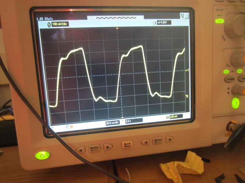
4. The Neo-Geo's CPU clock is ugly.
I scoped out the CPU clock on my MVS systems (MV-1C, MV-1, MV-4) and all of them are very noisy and non-square. It should be a nice square wave pulse, but it is in fact an ugly wave that is almost sinusoidal. Fine for the 68000, I suppose, but it caused some missed / repeated clocks on my FPGA dev boards I tried. A Schmidt trigger (74HC74) solved this issue, but it had be going crazy for a little while trying to determine what the hell was wrong with my design.
5. DAK and SHAD are poorly documented.
The Neo-Geo output has a pretty primitive resistor ladder DAC. While I am capturing SHAD and DAK, I'm not 100% sure what to even do with them. Right now I have determind which one is supposed to dim the screen (I test by writing a value to 0x3A0011 and 0x3A0001 and it does work) but within the 8-bit VGA DAC I'm using it won't really look correct. Eventually I plan on just building a duplicate of the original Neo-Geo DAC for output so it will be perfect. A non-issue, but I found it a little odd.
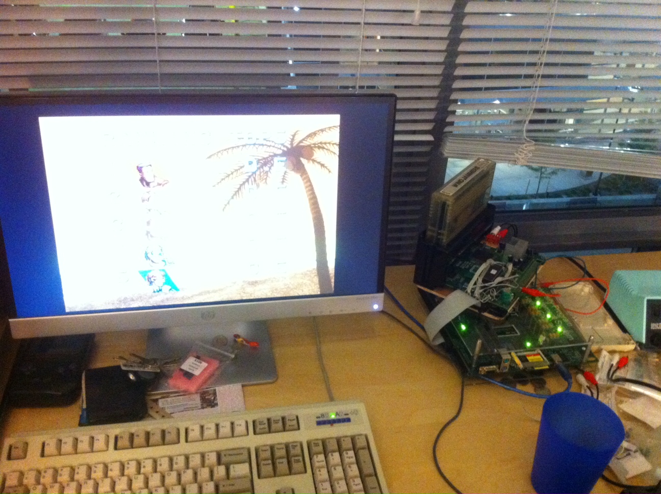
6. Your Vsync should be exactly two lines of time for 480 lines.
I had it a little too long, and the display did some weird skewing stuff on my CRT. On a Sony LCD television it was even weirder:
I made it two lines (768 CPU clock cycles) and it resolved itself.
Future Work
So, from here I'm not totally sure where I want to go. Right now the project is fairly stable, and even has a few tiny features like variable-intensity scanlines. However, once every now and then it will power up in a very odd state where the pixels will be captured all dirty, and flicker a bit on changing edges. I'm not sure of the cause. The next thing I will be doing is setting up a proper level converter, as right now I am passing my 5V levels into my 3.3V FPGA system, which is not great and I'm sure could cause issues in the future (though it is supposed to be 5V tolerant to some extent...). Perhaps this will improve things. Right now each line is a huge 384-position 17-bit shift register, which is not a great design, but it is what I am doing because I can not get block memory to be generated properly from ISE's IP core creator. My version of ISE is very old but nothing newer works on here, so it may be an actual bug.
I think it would be neat to develop a board in the same spirit as the NESRGB board - something for ~$100 that people who are really into their Neo-Geo MVS or AES systems could install in their board with some precise soldering, and enjoy a video output superior to current solutions. There are 22 lines that need to be soldered for it to work. It's not that bad, fortunately everything is pretty clearly laid out on the system. I haven't an AES so I have not tested there, but I do not see why it would not work.
I don't really know what is needed to go from the FPGA dev board to a proper separate board, though. If anyone is more experienced with this and has some pointers / recommendations, that would be appreciated. It doesn't use a lot of the FPGA's resources, so a smaller and cheaper one could be used. Certainly it will be many times cheaper than an XRGB system if finished. Some will cry out, "the GBS8200 works fine!" but I think if anyone is actually happy with a GBS8200 then they don't care much for video quality in the first place or don't want anything more expensive. I'd like for this to be $100 or lower. I'm using a Virtex-II Pro, which was new in 2003. Surely there are many old-stock or bare ones lying about, so this shouldn't have to be too expensive if a board was really produced.
Oh, here's a VERY high resolution of Windjammers with the 50% scanlines enabled: http://mikejmoffitt.com/img/neovga/v2psetup/wjammers.jpg
Anyway, if you have questions or suggestions I'd like to hear them. I'm not totally sure where to take this project from here, so any expressions of interest would be good motivation / a means to determine the future of it.
Last edited:
")
