bustedstr8
Trollbox Trade Federation,
- Joined
- Oct 15, 2007
- Posts
- 943
Glorious
Hi dudes,
This will be an internal DC VGA mod for a friend
[
Un saludo
")


As I see it, there are a few main benefits:
1) Direct boot of PS1 & PS2 backups. No swapping, trigger disc, or other exploit needed to play any and all PS1 games.
2) No ESR Patching PS2 games. ESR compatibility isn't perfect, and all PS2 games that you want to play from burned media will have to be ESR patched. CD based PS2 games will have to be converted into DVD format in order to be ESR patched.
3) No memory card exploits. You don't have to keep a memory card in your PS2 dedicated to the FreeMcboot exploit. Of course, you can also use the same memory card for PS2 saves, but ultimately, your entire mod exists on a memory card that can be wiped in an instant.
4) (Kinda falls into #1) Imports!!!! PS1 & PS2 pressed imports will boot directly! You can't do that with a softmod unless you disc-swap. The hassle simply isn't worth it to me.
This chip can be installed from the V1's all the way up to the last slim release.
The Modbo originally didn't support the V1-V3 boards, I was the one who assembled the correct pin-out by combining several 15 year old diagrams and probing with the 'ole meter.
This was the 1st ever pre V3 board to ever be chipped with a Modbo 4, fully operational.
http://theisozone.com/forum/viewtopic.php?f=78&t=45361

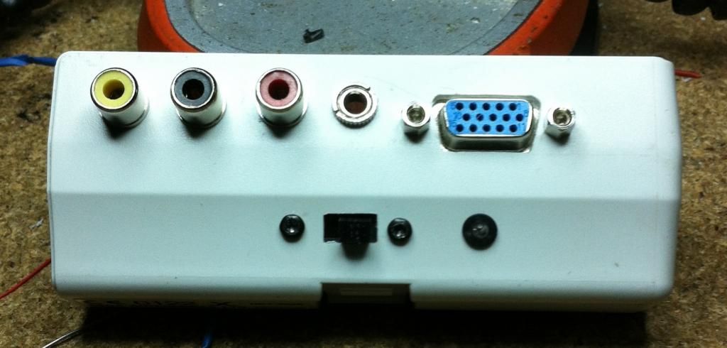
Is that Helder's new board? I could have used those switches on my last install...
Btw, I'd connect mono if I were you. It seems silly, but sometimes you get the itch to play and all you can find are the mono cables that the system came with or an rf switch.
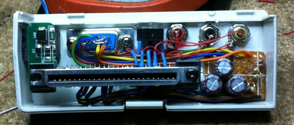
Why are there 3 giant blobs on the board?
Fellow member snes_collector sent in his v12 slim for some good 'ole mod-work.


He'll be a happy boy when he receives this.


Just finished this commission today;


I didn't realize my camera was blurry in some of these shots until everything was buttoned back up. Bleh.


Where do you source your S-video jacks? The ones I source locally here are these:
But I'd rather have the ones you're using.


