Madcatz Fightstick Pro TE - DB15 Neo Geo mod wth pictures

GohanX

Horrible Goose
20 Year Member
Joined
Sep 28, 2001
Posts
12,507
Guys, just thought I'd give you an update on the stick / mod - its working great, but in the meantime I also:
- got a Mega Drive and made a padhack box using soem Mega Drive pads to be able to use this stick on that console
- got a Blue Elf Jamma cart
While the stick behaved just fine with the Neo Geo MVS, with the above two devices it would either not function at all (Mega Drive) or behave eratically (Blue Elf)
The solution, which I found was that I needed to solder the +5V line to a +5V point on the stick (just follow the red line from the inside the USB connector cable). DOn't really know what the rationale for this is from a technical standpoint, but probably somethign to do with the fact that the USB hardware was still in the stick and in any case still connected with the switches / button contacts (along with the red lights displays for buttons etc. ) - maybe the whole thing was sapping too much power from the signal lines or something.

I am in the middle of building a multiconsole stick using a Madcatz TE with a 360 PCB and Cthulhu with a similar DB15 mod for Neo stuff and I was experiencing similar issues with the Neo side. The buttons would all register, but it was very erratic for no apparent reason. I believe you are correct with the power issue, mine was solved when I also plugged the USB cable into a power source, thus providing the PCBs with power. I haven't gotten around to hooking up the DB15 5V line yet.
 

MtothaJ

Host for Orochi
10 Year Member
Joined
Apr 15, 2013
Posts
756
I am in the middle of building a multiconsole stick using a Madcatz TE with a 360 PCB and Cthulhu with a similar DB15 mod for Neo stuff and I was experiencing similar issues with the Neo side. The buttons would all register, but it was very erratic for no apparent reason. I believe you are correct with the power issue, mine was solved when I also plugged the USB cable into a power source, thus providing the PCBs with power. I haven't gotten around to hooking up the DB15 5V line yet.

Thanks for sharing this.
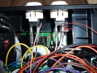
This is where I connected the +5V power line:

P1010808.JPG

Basically I used a continuity tester and checked where the power pin of the USB plug was connected to.
As for soldering the wire, space around this PCB is tight and there are plenty of wires / cables in the way. The sensible option would be to disassemble / disconnect the wires around this area, but you can also do a shortcut like in the below pic:

P1010810.JPG

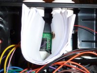
I just took a piece of standard white A4 paper, folded it enough times and then placed it like in the picture ti shield the cables. ALso what I did, but was already removed when I took the picture is I placed some black electrical tape on the other contact points below the +5V one to avoid any shortcircuting. Then basically went in there quick - placed some solder on the point and then reflowed that solder attaching the +5V line. Done two of these sticks this way and it is entirely safe - just need to make sure to have plenty of light (since the piece of paper casts a shadow and makes it hard to see whats going on) and don't leave the soldering iron in for too long (you will know that is the case when the paper starts charring up :very_ang::glee:).
 

xsq

Thou Shalt Not, Question Rot.,
Joined
Jan 17, 2013
Posts
7,414
Not against soldering up the 5V line from the DB15 at all, makes sense to me. But I was wondering if you couldn't also put a switch in there to choose which output is used?
 

MtothaJ

Host for Orochi
10 Year Member
Joined
Apr 15, 2013
Posts
756
Not against soldering up the 5V line from the DB15 at all, makes sense to me. But I was wondering if you couldn't also put a switch in there to choose which output is used?

Don't know if I understand correctly, but if you mean switching between USB and DB15 output then no switch is required in this regard - it will output to whatever device the joystick is plugged into (e.g. PS3 --> USB; Supergun --> DB15)
I guess you could have an issue if you would simultenously plug in both the DB15 and USB cables to different devices and power both on, but can't really see why one would want to do that in real life / what would be the point / need for such an excersie.
 

Mercuttio

Edo Express Delivery Guy
10 Year Member
Joined
Jun 7, 2013
Posts
340
It's kind of a stick-modding rule: you don't plug into two devices at once. But yeah, if you have a PCB involved in the setup (as the Madcatz does) you're going to need to use the 5V line on the DB15. I know the standard AES sticks don't use it, but I'm pretty sure everything else has to.
 
Last edited:

MtothaJ

Host for Orochi
10 Year Member
Joined
Apr 15, 2013
Posts
756
One thing which I noticed with the dual mod is that with the 5V connected to the stock PCB when using certain systems via DB15 eg. Neo Geo or a Sega Megadrive the autofire lights would turn on every so often and keep flashing seemingly at random - doesn't really effect gameplay but some could find it annoying I guess.
A different situation kept occuring with the Blue Elf board - here the autofire lights would flash and also autofire would at random turn on without the possibility of turning it off, meaning the whole thing wasn't really stable for that particular applciation.
Given that I don't use the stick much for PS3 (and I got another one dual modded just in case) I decided to bypass the PCB and make this a DB15 only stick.

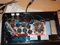
This is basically pretty simple - again you can get away without any soldering and it only takes a moment if you want to reinstate PS3 connectivity. Basically the PCB is connected to the stick / buttons by way of 3 plugs - one on the PCB from the joystick and two cables going from the PCB to 2 plugs on the terminal block. When you disconnect the 3 plugs you take the PCB out of the loop but you also loose common ground. So you need to reinstate common ground. I didn't take any photos so I will use one of the old ones:

schematic1.jpg

As mentioned the top row of the terminal block is the ground. The grounds in the whole terminal block is actually divided equally in half into two seperate circuits which would bridge together on the PCB so in this case you need to bridge e.g. the first ground on the leftmost end of the top row of the terminal block with the rightmost one also on the top row of the terminal block to ensure all the buttons have common ground. To that you need to add the ground from the actual stick, since that plug is disconnected also - just run a jumpwire from the ground on the stick to any one of the ground connections on the top row of the terminal block.

And thats pretty much it - no more flashing lights drama and eratic behaviour when playing bootleg emulated boards ;) If you want to use PS3 open the stick up and connect the 3 plugs back into place.
 
Last edited:
Top