Improve RGB signal in the first gen AES (NEO-AES) motherboard

OKI

Kabuki Klasher
Joined
May 11, 2006
Posts
126
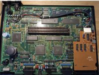
With the kind suggestion of Xian Xi, I post here a guide to improve the rgb
first version of the motherboard neogeo (NEO-AES).

Frontsostituzionecondensatoriprimaversoneschedaneogeo.jpg


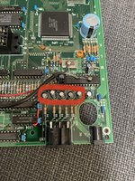
You should see 6 capacitors in a row in the top left corner. You do not change the first one which is 10uf. You change the other 5 100uf capacitors to 470uf 16v ones.

this will further improve the already good signal rgb on board
 

Xian Xi

JammaNationX,
15 Year Member
Joined
Dec 1, 2005
Posts
27,750
Make sure you add the pics after the update. If you still want to do the RGB bypass I can show you how as well.
 

OKI

Kabuki Klasher
Joined
May 11, 2006
Posts
126
Sure! I add the pics after the update. Yes please show me the procedure of bypass, so everyone can see.
 

Xian Xi

JammaNationX,
15 Year Member
Joined
Dec 1, 2005
Posts
27,750
The easiest way to do the RGB bypass is to remove the RGBS capacitors, they are #2-5 of the 6 capacitors from left to right. Then you just solder a wire from each top hole of the capacitor place and then solder the other side of the wire to the corresponding signal for that pin.

I'll post a pic later.
 

OKI

Kabuki Klasher
Joined
May 11, 2006
Posts
126
The easiest way to do the RGB bypass is to remove the RGBS capacitors, they are #2-5 of the 6 capacitors from left to right. Then you just solder a wire from each top hole of the capacitor place and then solder the other side of the wire to the corresponding signal for that pin.

I'll post a pic later.[/QUOTE

Sounds Good :)
 

F-zero

n00b
Joined
Mar 10, 2012
Posts
23
I would also remove the resistors on the rgb lines and place them in the scart lead instead.
This allows you to experiment with different resistors without worrying about the console.
I had to drop the resistors down to 37 0hms to brighten the picture to the point where i was happy.
The early revisions like the one i have produce dark rgb because the resistors are to strong for the signal.
 

thegreathopper

NAM-75 Vet
20 Year Member
Joined
Jun 3, 2002
Posts
1,009
I just carried out the RGB bypass mod bypassing all resistors and removing 4 caps, (RGB and Sync) but the picture was too bright and the picture rolled,

I then put the resistors back in circuit as the picture link above... thanks Xian Xi :-) and the picture is now great... plugged into a B&O MX4000 version 3.1

Thanks Guys.
 

thegreathopper

NAM-75 Vet
20 Year Member
Joined
Jun 3, 2002
Posts
1,009
Forgot to mention my mod is on a version one NeoGeo, the RGB picture was ok before the mod just not bright enough for my liking.

Now the colours pop :A: :B: :C: :D:
 

theboy995

n00b
Joined
May 4, 2017
Posts
14
hello everyone, I have an AES with a serial 10.xxx daughter board which the image is somewhat dark and reading I see that I would only have to change these capacitors marked in red of 100uf for ones of 470uf, would that be correct? Or would I have to do something else? I love her too much to break her, thank you!!!


E34779AD-55BB-4225-850F-BE73A5699575.jpeg
The easiest way to do the RGB bypass is to remove the RGBS capacitors, they are #2-5 of the 6 capacitors from left to right. Then you just solder a wire from each top hole of the capacitor place and then solder the other side of the wire to the corresponding signal for that pin.

I'll post a pic later.
 

Neo Alec

Ned's Ninja Academy Dropout
20 Year Member
Joined
Dec 7, 2000
Posts
11,996
For those using a Framemeister, just updating the A/D level is usually enough.

For everyone else, I can see how you may want to do it.

Are you talking about the power daughterboard with a voltage regulator on it, or the video daughterboard with a clock crystal?
 

theboy995

n00b
Joined
May 4, 2017
Posts
14
For those using a Framemeister, just updating the A/D level is usually enough.

For everyone else, I can see how you may want to do it.

Are you talking about the power daughterboard with a voltage regulator on it, or the video daughterboard with a clock crystal?
my board has both things on the daughter board

4D5492D2-31BE-4DBC-BB6A-41AF7226B050.jpeg
 

Neo Alec

Ned's Ninja Academy Dropout
20 Year Member
Joined
Dec 7, 2000
Posts
11,996
That's the video board. To improve the RGB, you should remove it and just move the crystal to the main board.


theboy995

n00b
Joined
May 4, 2017
Posts
14
That's the video board. To improve the RGB, you should remove it and just move the crystal to the main board.

thanks for the quick response Neo Alec

I did a test disconnecting the cable with the white connector to see how it would look, but the machine didn't even turn on, I imagine that board gives some energy too?

my rgb is good, but it looks a little dark, I don't need to just put the 5 capacitors of 470uf?
 

maki

Edo Express Delivery Guy
Joined
Jan 1, 2022
Posts
334
the image is somewhat dark
If anything the first model should be too bright, thats because they've used 68Ohm resistors instead of 75Ohm resistors (just nes tot the caps you've mentioned.

Whats cable are you using?
Cheap ebay cables will have components in them, when they shouldn't, thats going to make a dark picture.

The daughterboard mentioned is about improving the Composite Video, but sacrificing the RGB quality for it.
You could remove it by placing the crystal on the mainboard form the daughterboard, that will work, as was already mentioned by @Neo Alec
 

theboy995

n00b
Joined
May 4, 2017
Posts
14
If anything the first model should be too bright, thats because they've used 68Ohm resistors instead of 75Ohm resistors (just nes tot the caps you've mentioned.

Whats cable are you using?
Cheap ebay cables will have components in them, when they shouldn't, thats going to make a dark picture.

The daughterboard mentioned is about improving the Composite Video, but sacrificing the RGB quality for it.
You could remove it by placing the crystal on the mainboard form the daughterboard, that will work, as was already mentioned by @Neo Alec
Thanks Maki, well, it's not too bright, I have a 3-5 and it shines brighter, I use the rgb cable from retrogamingcables uk with csync, the rgb, as I say, I see well with sharpness and color, but as I comment, the image is somewhat dark, so if I changed the capacitors 100uf for those of 470uf would improve the brightness? thanks a lot
 

Neo Alec

Ned's Ninja Academy Dropout
20 Year Member
Joined
Dec 7, 2000
Posts
11,996
Thanks Maki, well, it's not too bright, I have a 3-5 and it shines brighter, I use the rgb cable from retrogamingcables uk with csync, the rgb, as I say, I see well with sharpness and color, but as I comment, the image is somewhat dark, so if I changed the capacitors 100uf for those of 470uf would improve the brightness? thanks a lot
Is the 3-5 modded? The mod instructions most follow provide a very bright picture.
 
Top