Could I trouble you to post a pic?
I know it's just a test version, but I'm planning the mods on my MVS cabinet and it would help to have an idea what it might look like. Is it just gonna be a board at the back of where an MV IC would normally be? Like, would it be possible to miss the card connector if you didn't plug it into the slot just so?
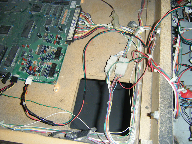
I have a dynamo hs-5 drawer cab, and I was gonna put a memory card sticker on a plate and route out a hole big enough for the card slot and memory card jacks in the center front of the drawer (think where that snarl of wires currently is across from the jamma connector):
Also, are you gonna make the cables, so we can plug it into the board the standard way, or is this gonna be some kinda solder mod that will make me cry myself to sleep?
 Yeah, NSM v2... put me down on the pre-order now.
")

")