You are using an out of date browser. It may not display this or other websites correctly.
You should upgrade or use an alternative browser.
You should upgrade or use an alternative browser.
jamma board sound issues (got sound, still issues though..any suggestions?)
- Thread starter NGT
- Start date
- Joined
- Mar 8, 2002
- Posts
- 3,686
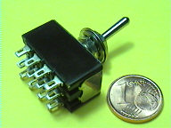
You could get a QPDT (quadruple pole-double throw) switch like this:
And wire it as in this scheme:
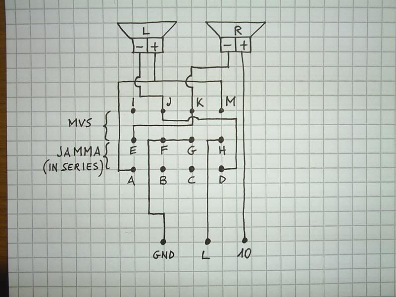
One position will be MVS, the other Jamma with sound from both speakers and a total impedence of 8ohm (good for jamma boards). Of course I'm assuming that the cab has two 4ohm speakers like official MVS cabs.
And wire it as in this scheme:
One position will be MVS, the other Jamma with sound from both speakers and a total impedence of 8ohm (good for jamma boards). Of course I'm assuming that the cab has two 4ohm speakers like official MVS cabs.
- Joined
- Jul 20, 2002
- Posts
- 4,762
MKL said:You could get a QPDT (quadruple pole-double throw) switch like this:
And wire it as in this scheme:
One position will be MVS, the other Jamma with sound from both speakers and a total impedence of 8ohm (good for jamma boards). Of course I'm assuming that the cab has two 4ohm speakers like official MVS cabs.
What I am not 100% on in that diagram:
--why when the jamma side is connected, does the speaker - goes to one speaker and the speaker + goes to the other.
Shouldn't they both go to one speaker?
--Also, why does the right speaker - connect to the left speaker + in jamma mode?
thanks!
sorry for not understanding this, but I am new to it.
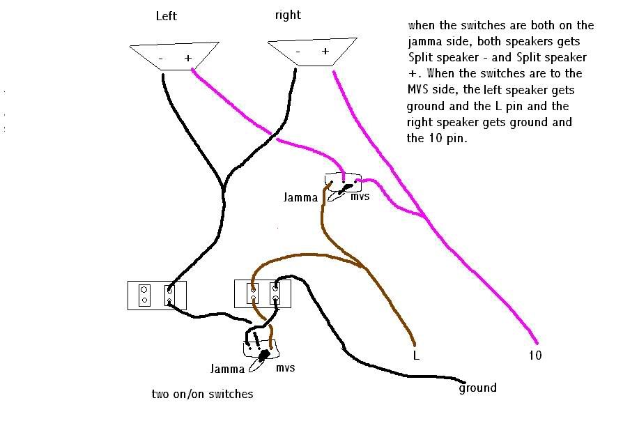
here's how mine is hooked up right now:
yeah, the ms paint looks like crap, but that's all I have and it's easy.
OH, and the diagram I made here has the "jamma" and "mvs" labels for the direction the actual switch would be pointing. Not to the pins for that setup.FOR EXAMPLE, when the switch is pointing towards the word JAMMA, it would be connecting the two pins on the opposite side of the switch, like a real switch would. hope that makes sense.
Starting from where I am at, would you suggest just having a switch that would cut off one of the speakers completely when in jamma mode? leaving one speaker getting speaker - and speaker + only?
Or am I ok where I am at?
ideas?
THANKS
Last edited:
- Joined
- Mar 8, 2002
- Posts
- 3,686
NGT said:What I am not 100% on in that diagram:
--why when the jamma side is connected, does the speaker - goes to one speaker and the speaker + goes to the other.
Shouldn't they both go to one speaker?
--Also, why does the right speaker - connect to the left speaker + in jamma mode?
Because that's how a series wiring is supposed to be:
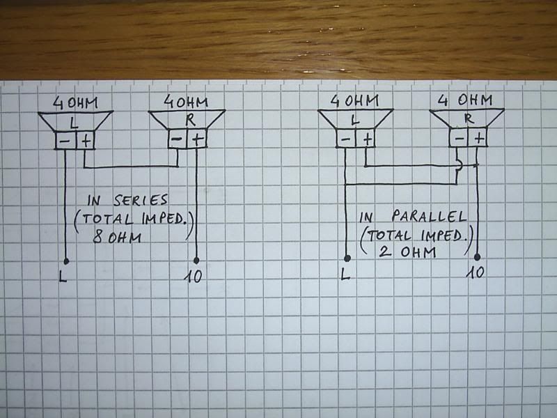
What you did is a parallel wiring, which is not good because the total impedence (2ohm) is too low for jamma boards amps.
Briggs
I'm getting too old for this shit...,
- Joined
- Oct 30, 2001
- Posts
- 2,277
MKL said:Forget about the screw and also forget about pin M: you probably read on that pdf on hardmvs that it is "audio ground" in the jamma pinout. That is misleading info: just ignore pin M when it comes to sound stuff.
How should it read? Is is misleading as in wrong? Or misleading as in not clear?
I honestly tend to stay away from the sound issue as I don't understand it, and I am very glad for this thread. I may try to put together a page with MKLs info (with his approval) as this seems to be one of the most asked questions
- Joined
- Mar 8, 2002
- Posts
- 3,686
Briggs, note 9 of your Jamma/MVS pinout pdf, about pin L (Speaker Negative = Ground/Common) is incorrect: as a rule, on Jamma boards pin L is a dedicated line coming from the amp and it's NOT ground. I've checked many boards and have yet to find one where L is ground. Therefore, identifying L with ground is incorrect.
As for pin M, reading "Audio Ground" in the pinouts, along with the other pins, gives the idea that it's something that *has* to be used when doing the audio wiring. The point is that a pin which is ground (but on which boards is pin M a ground?) should be simply called ground, without any further specification that would seem to imply that there are different types of grounds. This also holds for "Video Ground".
As for pin M, reading "Audio Ground" in the pinouts, along with the other pins, gives the idea that it's something that *has* to be used when doing the audio wiring. The point is that a pin which is ground (but on which boards is pin M a ground?) should be simply called ground, without any further specification that would seem to imply that there are different types of grounds. This also holds for "Video Ground".
I have another question concerning this.
The standard jamma "speaker resistance" is 8ohms, right? I have a mvs25up with two 8ohm speakers in it. They are connected separately (pin L to left speaker MINUS, pin 10 to right speaker MINUS and both speaker PLUS to common ground).
Do I need such a switch or can I just keep them connected like this as they are 8ohms instead of 4ohms as in the above example?
Is my setup not good as it is now for either jamma nor mvs? (the speakers and connections are just as they were when the cabinet left the factory in japan so it seems strange if the setup does not match the 6-slot board it was made for)
If i parallell connect my two speakers i get 4ohms, right?
If i parallell connect my two speakers i get 4ohms, right?
N
NeoGeoRich
Guest
Im having a similar problem. Im trying to get any sound at all from my Ninja Turtles JAMMA PCB. I just connected the harness from my MV1 slot and nothing. How do i just change it to mono?
ttooddddyy
PNG FTW,
- Joined
- Nov 29, 2001
- Posts
- 8,335
peap said:So here's my ideas.
Either I only use one speaker for jamma like this:

... or I use two speakers and half the impd. like this:

Please let me know what you think of these as I'm really tired now and may have missed important things.")
Both of those would work, preferably the bottom version as you would get sound out of both speakers for both MVS and straight Jamma with an impeadance of 4 ohms.
Some confusion lies with understanding the concept of bootlaced audio output stages, the same single mono/stereo output devices are wired differently for mono or stereo applications, as MKL points out, the vast majority of jamma boards do not have pin L grounded- check the block of the HA 13001 as used on both mvs (stereo) and jamma (mono) board sets.

Think of it not like a conventional audio hi fi speaker output, with + and - being ground, the zero cross over point is inbetween the two.
ttooddddyy
PNG FTW,
- Joined
- Nov 29, 2001
- Posts
- 8,335
The reason for boot lacing on jamma boards, or anywhere else ? Efficiency.
On the specs for this device (HA 13001 which is typical) the stereo application is 2 x 5.5 Watts (into 4 ohms) = 11 Watts total output
In mono mode the total is 17.5 Watts, more than 50% more power output running from one output (into a single 4 ohm load) compaired with the combined output into two speakers of similar impeadance.